Apparatus for making combination prints with pleasing appearance

a combination print and print technology, applied in the field of printing, can solve the problems of delay in printing, add significant costs to the printing process, and use of either form of finishing, and achieve the effect of reducing the visual impact of image artifacts

Inactive Publication Date: 2012-05-15
KODAK ALARIS INC
View PDF7 Cites 8 Cited by
  • Summary
  • Abstract
  • Description
  • Claims
  • Application Information

AI Technical Summary

Benefits of technology

[0015]Printers are provided. In one aspect, a printer has a printer controller cooperating with a print engine, receiver transport system, overlap positioning system, and fuser to cause a first toner image to be formed on the first side of the first receiver with toner at least in an overlap area proximate to a first edge of the first receiver; to overlap the first edge of the first receiver with a second edge of the second receiver having a second thickness at a second end and to fuse the overlapped first receiver and second receiver to cause the toner in the overlap area to bond the first receiver to the second receiver. The first toner image includes an edge concealment toner pattern positioned confronting the second edge with the edge concealment toner pattern having toner that reduces the visual impact of image artifacts created by the overlapping second edge.

Problems solved by technology

This adds significant costs to the process of printing using the requested receiver in that less frequently used receiver must be acquired and manually loaded before printing and because the manual loading process includes expenses for the labor required to locate and to load such receiver into the printer.
It will be appreciated that such manual processes can also lead to delays in printing.
The use of either form of finishing can add significant equipment or processing costs and / or can add significant processing time to the fulfillment of the print order.
Printing and cutting long sheets poses several limitations.
First, rolls of paper are heavy and hard to handle.
Both of these conditions detract from the appearance of a combined print.
Such artifacts are typically not acceptable to consumers who expect prints to be recorded on a continuous receiver.
A step of such height also creates a catch point that can cause damage to the bound sheets if mechanically engaged while the combination print is being moved.

Method used


Image

  • Apparatus for making combination prints with pleasing appearance
  • Apparatus for making combination prints with pleasing appearance
  • Apparatus for making combination prints with pleasing appearance

Examples


first embodiment

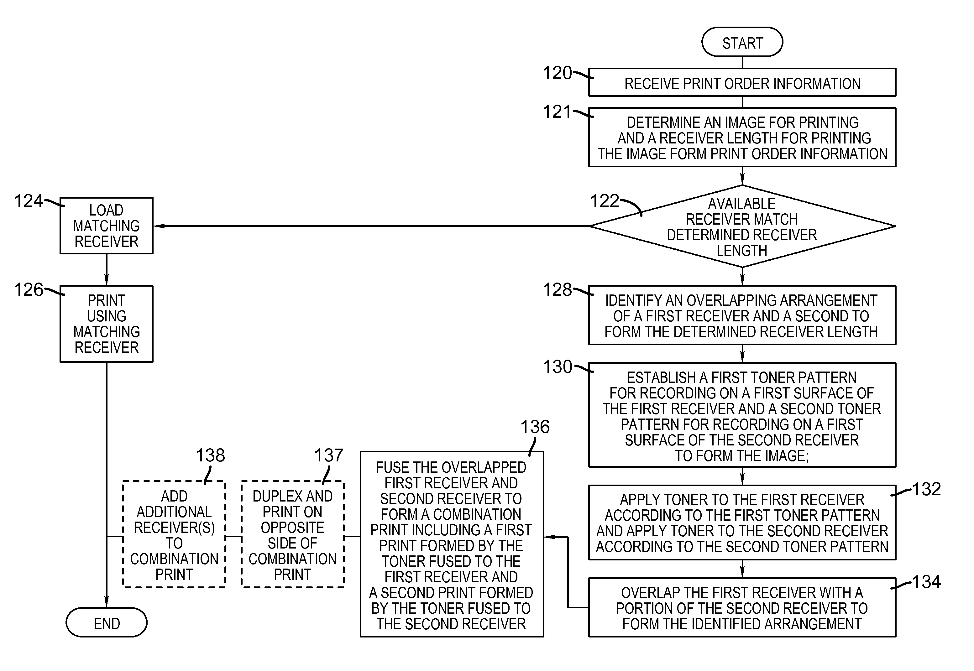
[0066]FIG. 3 shows a flow chart depicting first embodiment of a method for forming prints of a determined length. As is shown in the embodiment of FIG. 3, in a first step, a print order is received including information from which an image to be printed and a receiver length L for printing the image can be determined. The print order can be received, for example, from communication system 90, user input system 84, or memory 88 (step 118).

[0067]Printer controller 82 uses the information in the print order to determine an image for printing and a length of receiver L to be used in printing the image (step 120). In this regard, the print order can generally comprise any type of data or instructions that printer controller 82 can use to determine an image for printing and a length L of the receiver onto which the determined image is to be printed. For example, and without limitation, the print order can comprise image data such as an image data file that defines the determined image and...

second embodiment

[0159]In a second embodiment, shown in FIG. 21, an edge concealment toner pattern 360 is applied in separate layers as can be applied by passing first receiver past print engine 22 more than once. For example, a first layer 372 of a masking toner 362 can be applied using a toner that matches the color of first receiver 26a or second receiver 26b. Where this is done, a second layer 374 of image forming toner can be applied in one or more additional layers formed over the first layer 372. For example, where first receiver 26a and second receiver 26b are white paper type receivers first layer 372 could be formed from a white toner, such as would be obtained with toner particles containing high dielectric constant materials such as TiO2, BaTiO3, or SrTiO3 while second layer 374 having first toner image 25a can be applied with an imaging pattern.

[0160]In other embodiments, a portion of the edge concealment toner pattern 360 can be provided on second edge 192 of second receiver 26b during...


PUM


Abstract

Printers are provided. In one aspect, a printer has a printer controller cooperating with a print engine, receiver transport system, overlap positioning system, and fuser to cause a first toner image to be formed on the first side of the first receiver with toner at least in an overlap area proximate to a first edge of the first receiver; to overlap the first edge of the first receiver with a second edge of the second receiver having a second thickness at a second end and to fuse the overlapped first receiver and second receiver to cause the toner in the overlap area to bond the first receiver to the second receiver. The first toner image includes an edge concealment toner pattern positioned confronting the second edge with the edge concealment toner pattern having toner that reduces the visual impact of image artifacts created by the overlapping second edge.

Description

CROSS REFERENCE TO RELATED APPLICATIONS[0001]This application relates to commonly assigned, copending U.S. application Ser. No. 12 / 846,651, filed Jul. 29, 2010, entitled: “A METHOD FOR FORMING DURABLE COMBINATION PRINTS”; U.S. application Ser. No. 12 / 846,660, filed Jul. 29, 2010, entitled: “APPARATUS FOR FORMING DURABLE COMBINATION PRINTS”; U.S. application Ser. No. 12 / 846,634, filed Jul. 29, 2010, entitled: “A METHOD FOR MAKING COMBINATION PRINTS WITH PLEASING APPEARANCE”; U.S. application Ser. No. 12 / 846,623, filed Jul. 29, 2010, entitled: “A METHOD FOR FORMING A COMBINATION PRINT WITH CONTINUOUS IMAGING” and U.S. application Ser. No. 12 / 846,611, filed Jul. 29, 2010, entitled: ‘OVERLAP POSITIONING SYSTEM” each hereby incorporated by reference.FIELD OF THE INVENTION[0002]This invention pertains to the field of printing.BACKGROUND OF THE INVENTION[0003]Sheet fed digital printers are capable of storing only limited numbers of different types of receivers. However, with increased use ...

Claims


Application Information

Patent Timeline
Patent Type & Authority Patents(United States)
IPC IPC(8): G03G15/01G03G15/00
CPCG03G15/6594G03G15/6541B42C9/0093
Inventor LAWNICZAK, GARY P.RIMAI, DONALD S.
Owner KODAK ALARIS INC
Why Eureka
Try Eureka