Float for liquid level indicator

a liquid level indicator and floating technology, applied in liquid/fluent solid measurement, instruments, machines/engines, etc., can solve the problems of general inability to meet the requirements of liquid level indicators of magnetic floating types, and achieve the effect of satisfying the needs of users and reducing the number of indicators

Active Publication Date: 2012-05-22
DONEHUE WADE L
View PDF3 Cites 5 Cited by
  • Summary
  • Abstract
  • Description
  • Claims
  • Application Information

AI Technical Summary

Benefits of technology

[0004]It is an object of this invention to provide a magnetic float for a liquid level indicator which provides satisfactory service in high pressure, low liquid density applications.

Problems solved by technology

Prior art level indicators of the magnetic float type were generally not satisfactorily reliable in situations where high pressure surrounded the float and / or where the liquid carrying the float was of low density.
Liquefied light hydrocarbons commonly exist as low density liquids in high pressure vessels in the petroleum and petrochemical industries and heretofore have not lent themselves well to level measurements with magnetic float devices.

Method used


Image

  • Float for liquid level indicator
  • Float for liquid level indicator
  • Float for liquid level indicator

Examples


Embodiment Construction

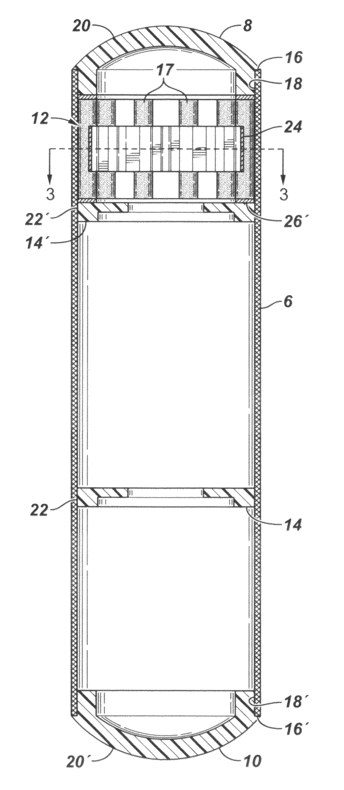
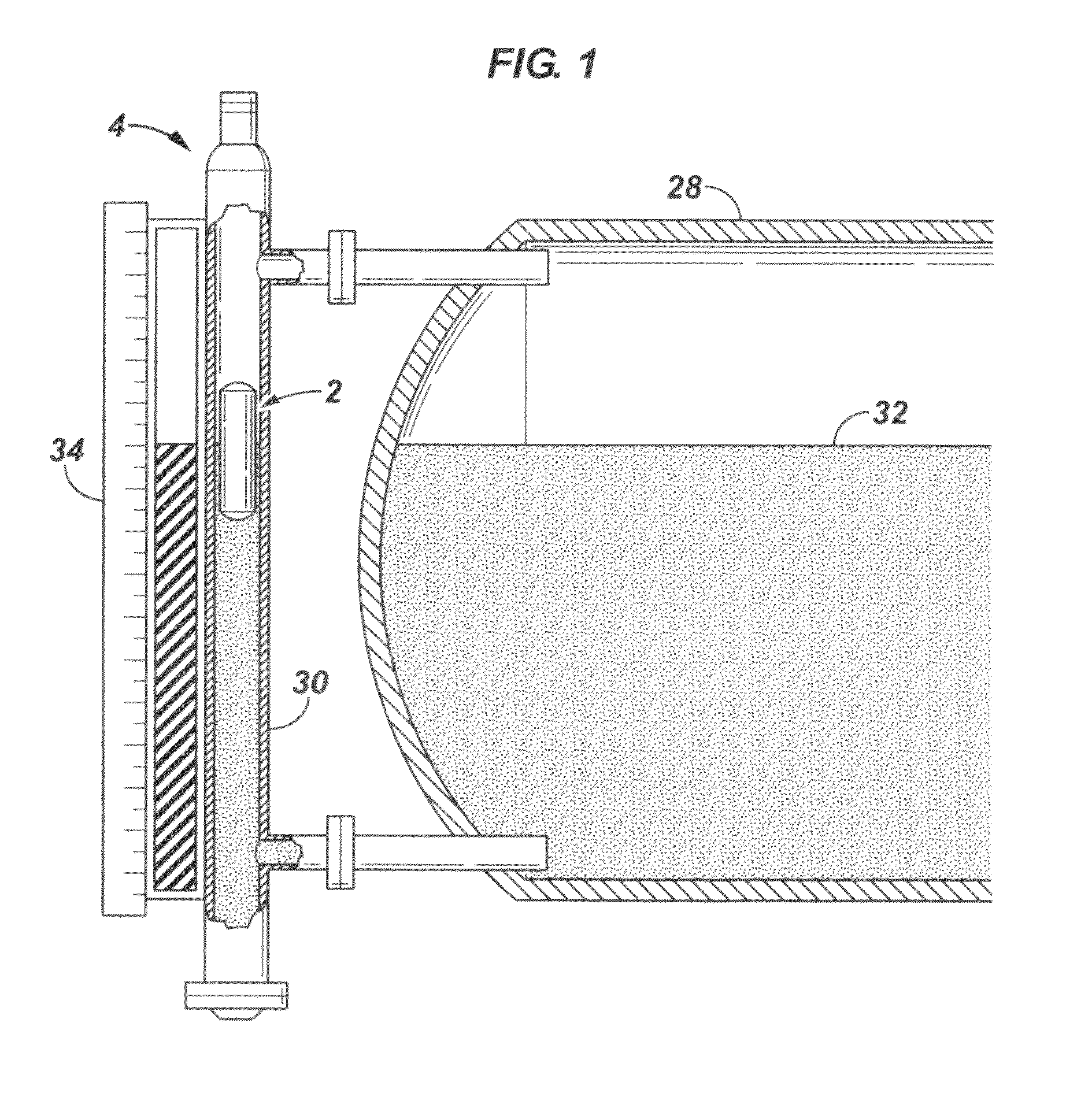
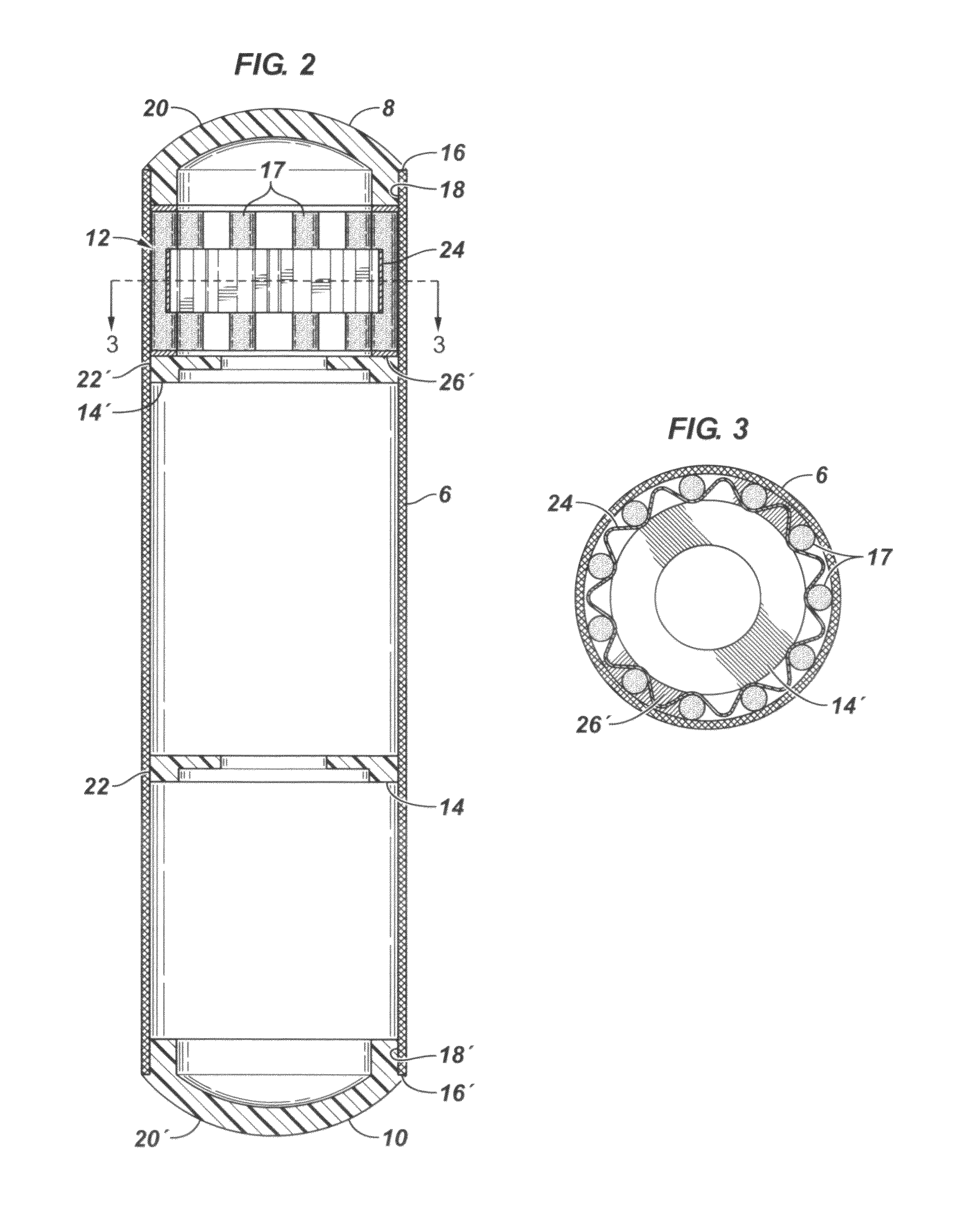
[0010]In one embodiment of the invention, there is provided a magnetic float 2 for a level indicator system 4. The float comprises a hollow tube, first and second endcaps 8 and 10, and a magnet assembly 12

[0011]The hollow tube comprises a carbon fiber reinforced cured resin matrix and has a first end, a second end, and a longitudinal axis extending between the ends. The first and second endcaps are formed from polymer and are dome-shaped. They seal the first and second ends of the hollow tube, respectively, to hermetically seal the inside of the float the outside.

[0012]At least one polymeric reinforcing ring 14 is mounted inside of a midsection of the hollow tube between the first end and the second end to resist radial inward collapse of the tube. In the illustrated embodiment, a second reinforcing ring 14′ is mounted near the first end of the tube to position the magnet assembly against the first endcap.

[0013]The magnet assembly is mounted in the tube near the first endcap and com...


PUM


Abstract

A magnetic float is provided for a level indicator system that is suitable for low density liquids at high pressure, such as C3-liquids. The float comprises a hollow tube, first and second endcaps, and a magnet assembly. The hollow tube comprises a carbon fiber reinforced cured resin matrix and has a first end, a second end, and a longitudinal axis extending between the ends. The first and second endcaps are formed from polymer and dome-shaped. They seal the first and second ends of the hollow tube, respectively, to hermetically seal the inside of the float the outside. At least one polymeric reinforcing ring is mounted inside of a midsection of the hollow tube between the first end and the second end to resist radial inward collapse of the tube. The magnet assembly is mounted in the tube near the first endcap and comprises a plurality of longitudinally elongated magnets positioned adjacent the inside wall of the hollow tube. Each magnet has a longitudinal axis positioned parallel to the longitudinal axis of the hollow tube and is circumferentially spaced from the other magnets.

Description

FIELD OF THE INVENTION[0001]In one aspect, this invention relates to a float for liquid level indicator of the type having a magnetized float which moves as the level of liquid changes.BACKGROUND OF THE INVENTION[0002]Liquid level indicators which employ a magnetized float generally employ one or more optical indicator elements triggered by the magnets in the float and / or another type of magnetic proximity sensor such as a magnetostrictive wire operating to produce a level signal in a readout device.[0003]Prior art level indicators of the magnetic float type were generally not satisfactorily reliable in situations where high pressure surrounded the float and / or where the liquid carrying the float was of low density. Liquefied light hydrocarbons commonly exist as low density liquids in high pressure vessels in the petroleum and petrochemical industries and heretofore have not lent themselves well to level measurements with magnetic float devices.OBJECTS OF THE INVENTION[0004]It is an...

Claims


Application Information

Patent Timeline
Patent Type & Authority Patents(United States)
IPC IPC(8): G01F23/76G01F23/72
CPCG01F23/72G01F23/76
Inventor DONEHUE, WADE L.
Owner DONEHUE WADE L
Why Eureka
Try Eureka