
Method for removing lint from a heat exchanger of a domestic appliance and corresponding domestic appliance

a technology for domestic appliances and heat exchangers, applied in the field of tumble dryers, can solve the problems of difficult cleaning, difficult cleaning, and difficult cleaning per se, and achieve the effects of simple cleaning process, easy cleaning, and simple cleaning process

Inactive Publication Date: 2012-05-22
BSH BOSCH & SIEMENS HAUSGERAETE GMBH
View PDF9 Cites 35 Cited by
  • Summary
  • Abstract
  • Description
  • Claims
  • Application Information

AI Technical Summary

Benefits of technology

[0007]With the inventive method for removal from a heat exchanger of lint generated during a drying process of a domestic appliance for laundry care, a rinsing liquid is conveyed through the heat exchanger. The rinsing liquid is diverted during a cleaning phase depending on the strength of an air flow able to be generated and, depending on this diversion, the rinsing liquid flows through the various areas of the heat exchanger. This enables the removal of lint from the heat exchanger to be achieved highly effectively. By the rinsing liquid being directed individually to different points of the heat exchanger, practically all areas of the heat exchanger can be freed from lint. This enables not just a relatively simple and straightforward process but also improved cleaning to be guaranteed. Deposits on the fins of the heat exchanger both in its front and in its rear area are thus removed by this efficient cleaning. The performance data of the device, especially the energy consumption and the time required are optimized by this method. In addition it is no longer necessary to undertake any other mandatory cleaning of filter systems.
[0016]The rinsing liquid is preferably introduced from above into the heat exchanger and then circulates through the fins of the heat exchanger. The high flow speed and the opportunity of introducing a relatively large quantity of liquid achieved in this way allows the lint adhering to be rinsed off effectively.

Problems solved by technology

Since the filter systems are installed in the area of the base of the device however, maintaining them involves a very tedious process.
In addition the cleaning cycles are relatively short and cleaning is very complicated per se.

Method used


Image

  • Method for removing lint from a heat exchanger of a domestic appliance and corresponding domestic appliance
  • Method for removing lint from a heat exchanger of a domestic appliance and corresponding domestic appliance

Examples


Embodiment Construction

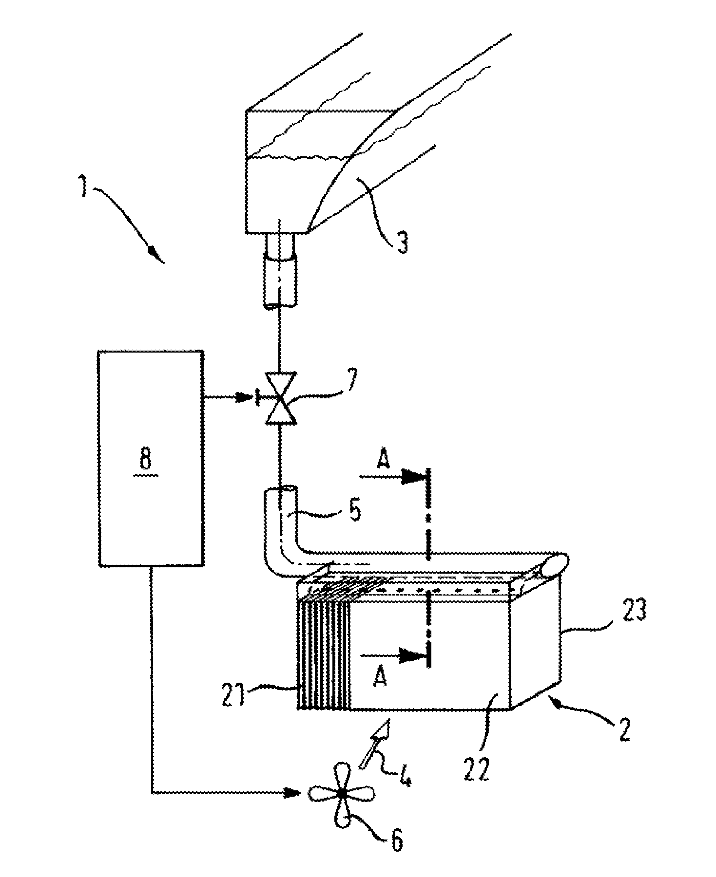
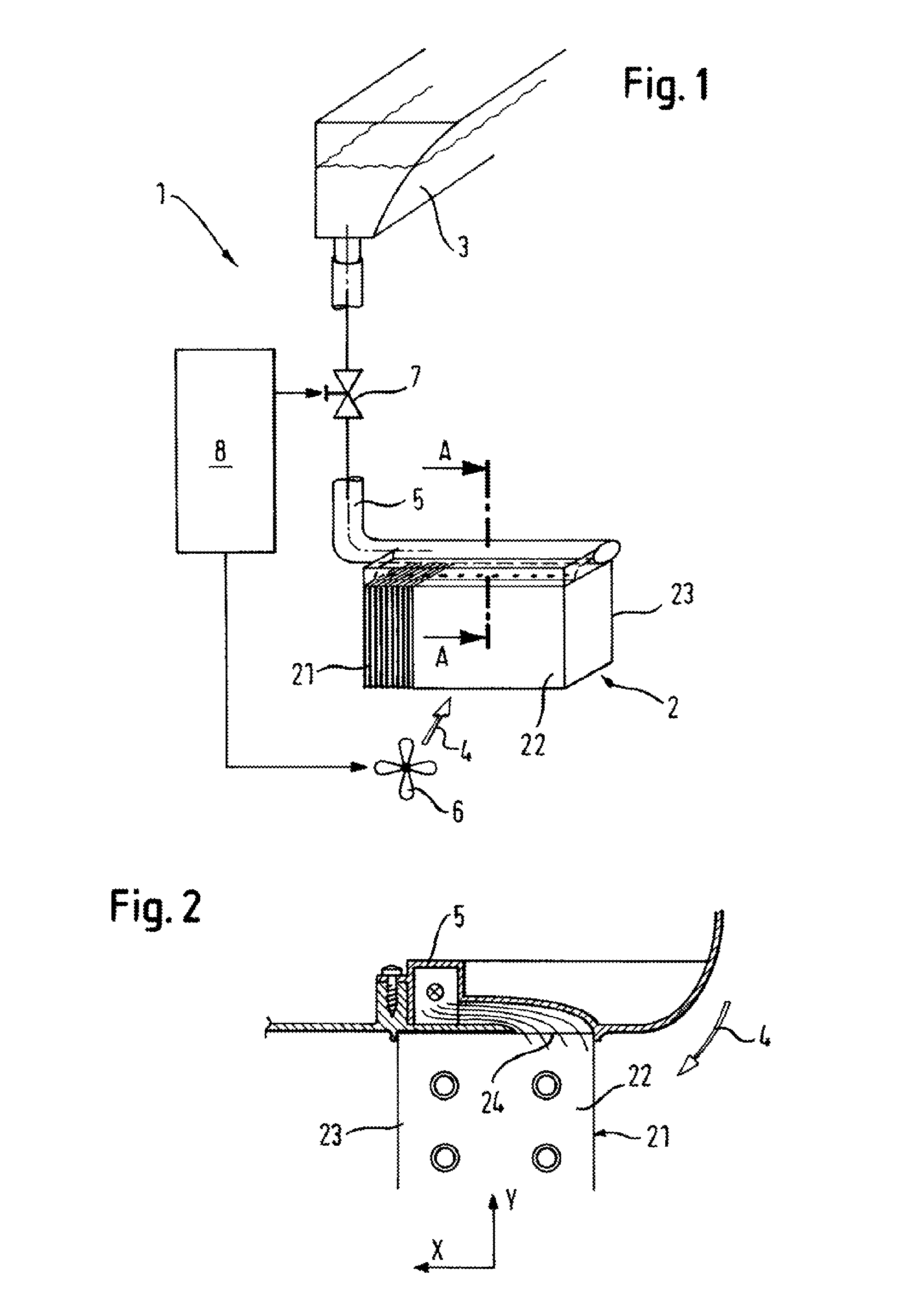
[0021]In the figures elements which are the same or have the same functions are provided with the same reference numbers.

[0022]A tumble dryer 1 comprises a compressor heat pump 2 (cf. above description; only shown in part here for reasons of clarity) which comprises a heat exchanger 2. The heat exchanger 2 comprises a plurality of fins 21 and is coupled to a process air guide. The result able to be achieved by this is that during operation of the tumble dryer 1, especially during the drying phase, process air is directed as a flow of air 4 in the direction shown by the arrow through the heat exchanger 2. The air flow 4 generated in the process air guide is generated by a process air blower 6 depicted only schematically in the diagram, which can be activated and deactivated as required.

[0023]In addition the tumble dryer 1 includes a collection vessel 3 which is arranged in a vertical direction on a higher level than the heat exchanger 2. In the collection vessel 3 there is condensate...


PUM


Abstract

A method is provided for the removal from a heat exchange of lint that is generated during a drying process in a domestic appliance for laundry care. A rinsing fluid is run through the heat exchanger for cleaning and the rinsing fluid is deflected during a cleaning phase with the magnitude of deflection or the direction of deflection of the rinsing fluid being a function of the strength of an air flow that is applied to deflect the rinsing fluid. The rinsing fluid is thus run through various regions of the heat exchanger depending on the deflection.

Description

BACKGROUND OF THE INVENTION[0001]The invention relates to a method for the removal of lint, generated during the drying process in a domestic appliance, especially a tumble dryer, for laundry care, from a heat exchanger, wherein a rinsing fluid is run through the heat exchanger for cleaning.[0002]The invention also relates to a domestic appliance for laundry care, comprising a heat exchanger, a process air blower for driving an air flow through the heat exchanger, a collection vessel for a rinsing liquid for removal of the lint generated during the drying process from the heat exchanger, whereby in a cleaning phase the rinsing liquid is conveyed through the heat exchanger, as well as a control device for controlling the cleaning.[0003]A method as well as a domestic appliance of this type are known from DE 37 38 031 C2.[0004]In addition tumble dryers are known which feature a compressor heat pump for alternate heating up and cooling down of a circulating flow of process air. In addit...

Claims


Application Information

Patent Timeline
IPC IPC(8): B08B3/04
CPCD06F58/20D06F58/24
Inventor GRUNERT, KLAUS
Owner BSH BOSCH & SIEMENS HAUSGERAETE GMBH
Learn More