Hollow fiber membrane separation device

Active Publication Date: 2012-05-22
FRESENIUS MEDICAL CARE DEUTSCHLAND GMBH
View PDF14 Cites 12 Cited by
  • Summary
  • Abstract
  • Description
  • Claims
  • Application Information

AI Technical Summary

Benefits of technology

[0008]Therefore, it is the object of the present invention to further develop a hollow fiber membrane sep

Problems solved by technology

Such housings which are formed with the tooth-like or pinnacle-like projections have, however, the drawback that, during the manufacture of the hollow fiber membrane separati

Method used


Image

  • Hollow fiber membrane separation device
  • Hollow fiber membrane separation device

Examples


Embodiment Construction

[0021]Further scope of applicability of the present invention will become apparent from the detailed description given hereinafter. However, it should be understood that the detailed description and specific examples, while indicating preferred embodiments of the invention, are given by way of illustration only, since various changes and modifications within the spirit and scope of the invention will become apparent to those skilled in the art from this detailed description.

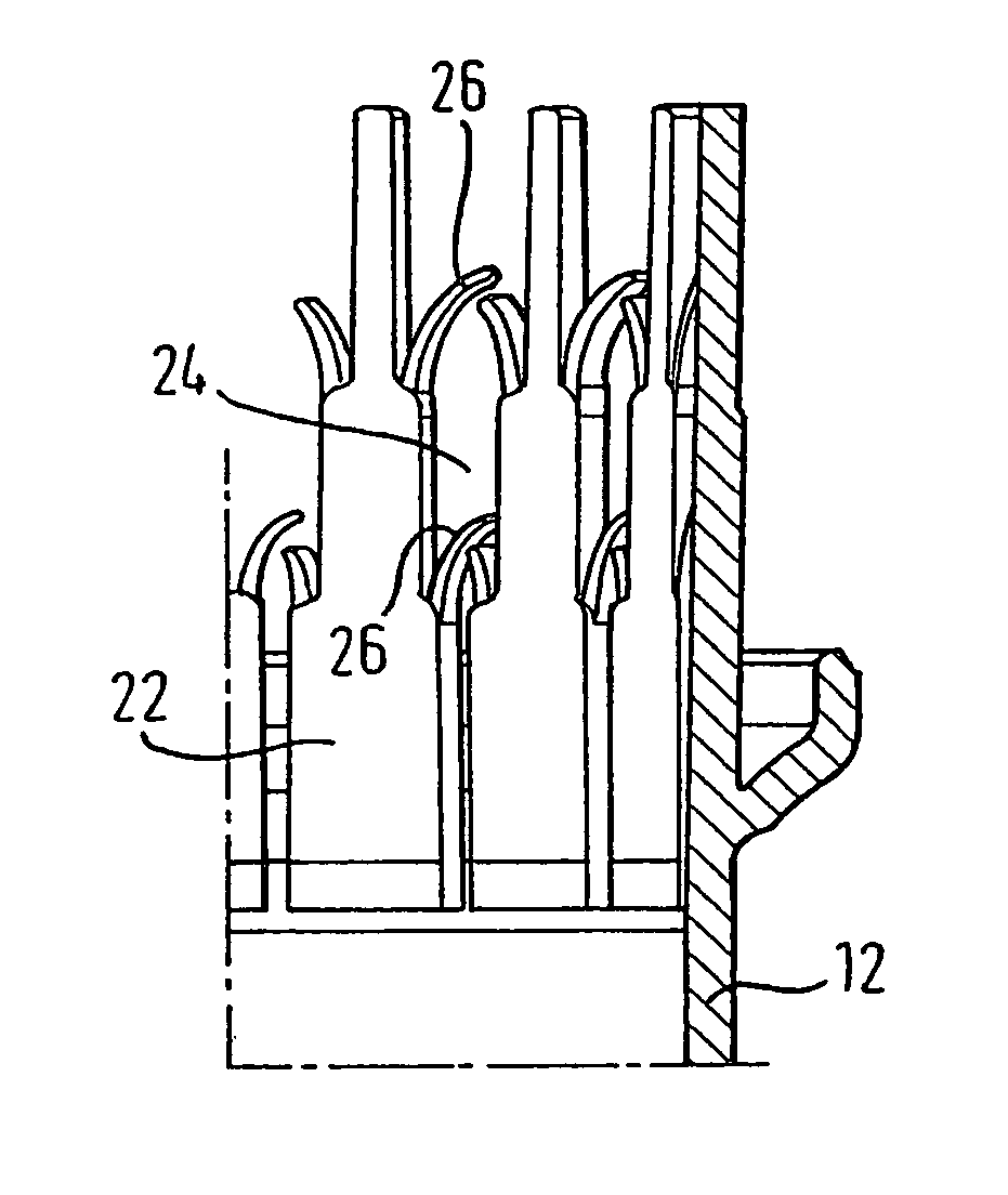
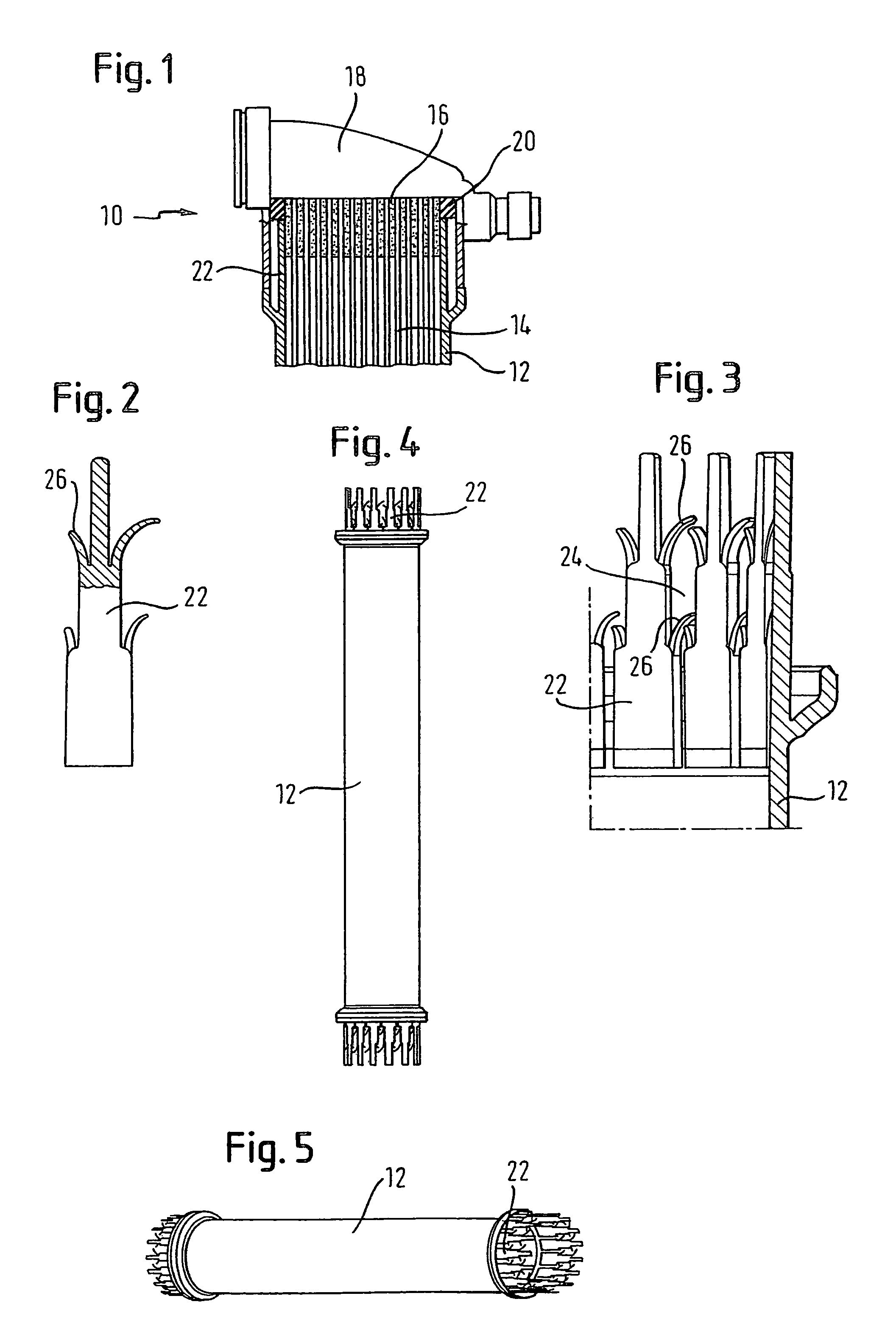
[0022]The hollow fiber membrane separation device 10 consists of a pipe-section-shaped housing 12 made of plastic material, for instance polycarbonate. A hollow-fiber bundle is inserted into the housing. The ends of said hollow fiber membrane bundle 14 are embedded in a sealing compound 16, for instance consisting of PU, which has a disk shape after its hardening. By means of the sealing compound 16, the hollow fibers 14 are joined to the housing 12.

[0023]A cap 18 is placed on the housing, said cap being sealed o...


PUM

PropertyMeasurementUnit
Flexibilityaaaaaaaaaa
Heightaaaaaaaaaa

Abstract

A hollow fiber membrane separation device with two flow spaces, of which a first space is formed by the capillary tube passages of a hollow-fiber bundle cast at its ends into a sealing compound, and a second space is formed by a housing enclosing the fiber bundle. The first space is sealed off by caps, placed on the sealing compounds, with seals running over the peripheral areas of the sealing compounds. The housing, into which the hollow-fiber bundle is drawn, at each end of its casing has tooth-like or pinnacle-like projections formed by axial notches or indentations running out freely. The tooth-like or pinnacle-like projections have extensions extending from the sides of the projections and extending to the adjacent tooth-like or pinnacle-like projection.

Description

[0001]This is a national stage of PCT / EP06 / 005507 filed Jun. 8, 2006 and published in German, which claims priority of German application 10 2005 043321.9, filed on Sep. 12, 2005.BACKGROUND OF THE INVENTION[0002]1. Field of the Invention[0003]The present invention refers to a hollow fiber membrane separation device with two flow spaces, of which a first space is formed by the capillary tube passages of a hollow-fiber bundle cast at its ends into a sealing compound, and a second space is formed by a housing enclosing the fiber bundle, in which the first space is sealed off by caps placed on the sealing compounds, and in which the housing, into which the hollow-fiber bundle is drawn, at each end of its casing has tooth-like or pinnacle-like projections formed by axial notches or indentations running out freely.[0004]2. Description of the Related Art[0005]Hollow fiber membrane separation devices of said kind are for instance known from EP-A-0 844 015. In said hollow fiber membrane sepa...

Claims


Application Information

Patent Timeline
IPC IPC(8): B01D63/00C02F1/44
CPCB01D63/02B01D2313/20
Inventor WITTHAUS, FRIEDRICHBREITH, GERHARD
Owner FRESENIUS MEDICAL CARE DEUTSCHLAND GMBH
Why Eureka
Try Eureka