
Acoustic echo cancellation for time-varying microphone array beamsteering systems

a technology of microphone array and beamsteering system, which is applied in the direction of transducer casing/cabinet/support, transducer, electric transducer, etc., can solve the problems of frequent instantaneous echo path change in the pace of natural conversation, change in the acoustic echo path at the beamformer output, etc., and achieve the effect of reducing echo and nois

Inactive Publication Date: 2012-05-22
NOKIA CORP
View PDF4 Cites 46 Cited by
  • Summary
  • Abstract
  • Description
  • Claims
  • Application Information

AI Technical Summary

Benefits of technology

[0032]In a first aspect, a method for reducing echo and noise is provided. In another aspect a mobile terminal device having a processing and memory unit for providing an acoustic echo cancellation and a micro-phone beamforming is provided. In a further aspect, a beamforming system for a mobile terminal device is provided. In another aspect, a client and a server in a client-server network suitable for acoustic echo cancellation are provided. In a fourth aspect, a module of a beamforming system is provided; a signal processor is provided; a semiconductor integrated circuit is pr

Problems solved by technology

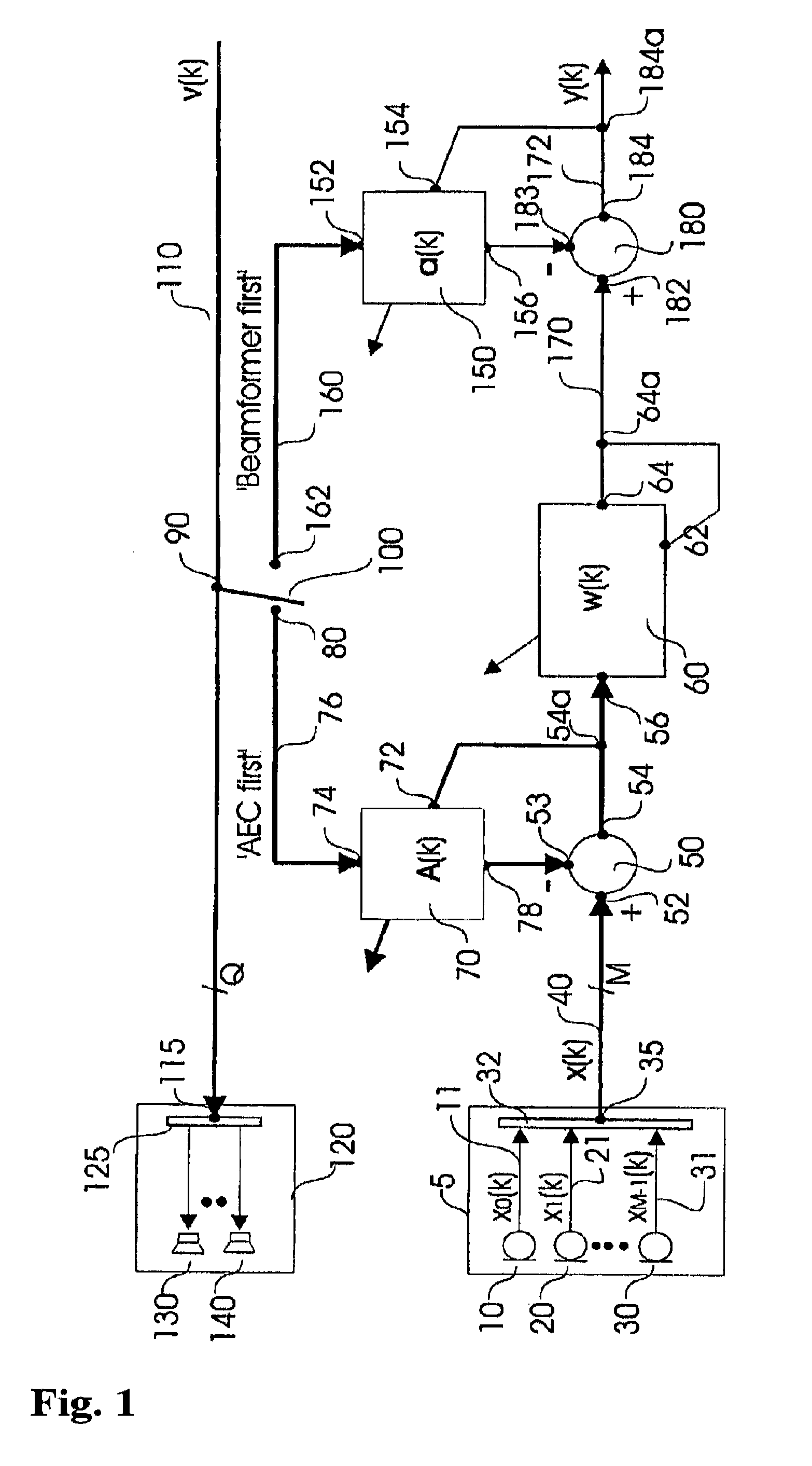
The problem arises when the adaptive filter of the AEC system tries to model (favorably relatively time-invariant) echo path and at the same time speaker tracking function of the microphone array is changing the beamforming filter directivity causing changes in the acoustic echo path at the beamformer output.
This could lead to frequent instantaneous echo path changes in the pace of the natural conversation.

Method used


Image

  • Acoustic echo cancellation for time-varying microphone array beamsteering systems
  • Acoustic echo cancellation for time-varying microphone array beamsteering systems
  • Acoustic echo cancellation for time-varying microphone array beamsteering systems

Examples


first embodiment

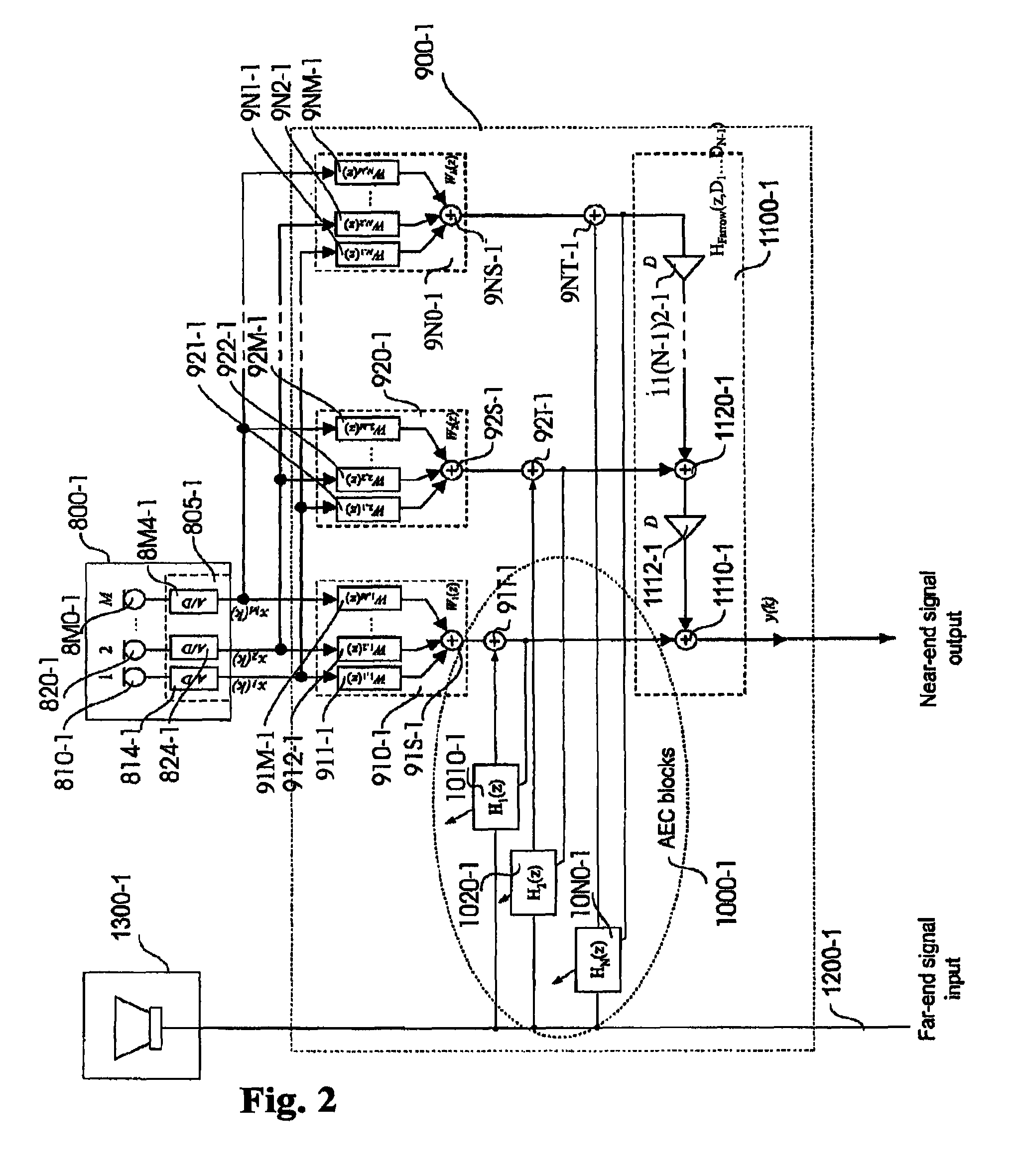
[0090]In this first embodiment the output section is simplified by for comprising only one speaker. But may be appreciated that the features substantiated for the input side, especially for the signal converters are also applicable for the output side.

[0091]Note that the signal converter may be a part of a signal processor or semiconductor of a type capable to output a power signal directly to a speaker, for example using a high-clocked 1 bit data signal feeding a pulse width modulation power amplifier, wherein the speaker or the frequency response of the environment may acts as reconstruction low pass.

[0092]In FIG. 2, each channel of said input block 800-1 may be connected with each pre-filter 910-1, 920-1, 9N0-1, for example, in the following way, using an algorithm of connecting like matrix-connecting as follows:[0093]such that a first output of said input block 800-1 having a signal x1(k) (for example a representation of a first data stream) is connected with the first input of ...

second embodiment

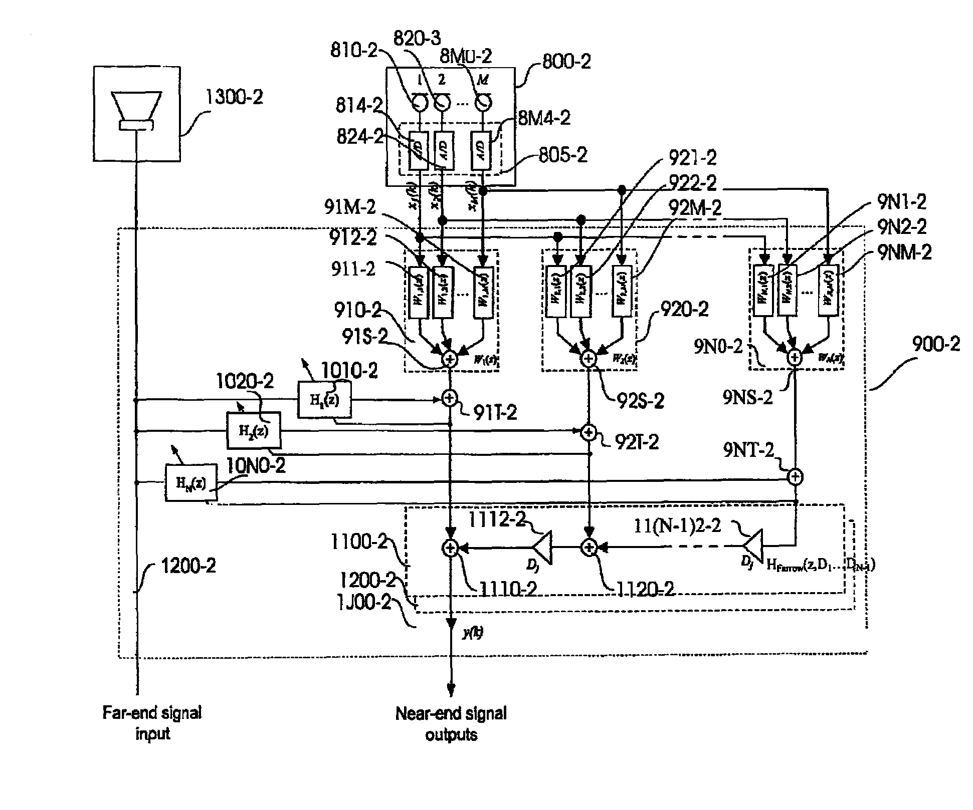
[0118]In FIG. 5 a proposed AEC integration to time-varying PBF beamformer front-end with multiple output beams is shown according to the present invention.

[0119]Note that all reference signs have a “−2” at the end, according to the second embodiment, but the here a plurality of parallel post-filters is present e.g. for the tracking of multiple dynamic sources. For the rest the same components are used as shown in FIG. 2.

[0120]According to FIG. 6 a third embodiment for a proposed AEC integration to time-varying PBF beamformer front-end with multiple loudspeakers and multiple output beams is shown. This MIMO implementation calls for multi-channel echo cancellation methods known in the art. All reference signs have a “−3” at the end, according to the third second embodiment, for the rest the same components are used as shown in FIG. 2.

[0121]In FIG. 7, the fourth embodiment integrates AEC with a time-varying PBF beamformer with partitioned AEC structure. In this embodiment AEC filters H...

fourth second embodiment

[0122]This embodiment can also be extended for multiple beams and output signals (see FIG. 5) and multiple loudspeakers (MIMO configuration) (see next Embodiment in FIG. 8). All reference signs have a “−4” at the end, for the rest the same components are used as shown in FIG. 2.

[0123]FIG. 8 shows a fifth Embodiment which is an extension of the fourth embodiment with multi-channel MIMO configuration. Respective reference signs have a “−5” at the end, according to the fifth second embodiment, for the rest the same components are used as shown in FIG. 5.


PUM


Abstract

In a mobile terminal device having a processing unit and a memory unit, an acoustic echo cancellation and a microphone beamforming are provided. Said device includes a plurality of a microphones, a pre-processing stage has an amplifier and a signal converter for an analog-to-digital conversion. In a main signal processing stage, a pre-filter suitable for polynomial beamforming, an acoustic echo cancellation stage and a post-filter for polynomial beamforming are provided. Furthermore, a post-processing stage has an amplifier and a signal converter for a digital-to-analog conversion, and plurality of speakers.

Description

CROSS REFERENCE TO RELATED APPLICATIONS[0001]This patent application claims priority under 35 U.S.C. §119(e) from Provisional Patent Application No. 60 / 932,981 filed Jun. 29, 2006, which, in accordance with a Request For Conversion Under 37 C.F.R. §1.53(c)(2) filed on Jun. 14, 2007, was converted from U.S. patent application Ser. No. 11 / 479,241, filed Jun. 29, 2006, the disclosure of which is incorporated by reference herein in its entirety.AREA OF THE INVENTION[0002]The present invention generally relates to a cancellation of an acoustic signal, for example a cancellation of an acoustic echo or feedback frequencies in a room and to a beamforming (including beam steering), for a plurality of microphones, for example an array of microphones, for example in mobile communications.BACKGROUND OF THE INVENTION[0003]Echo cancellation and beamforming can be used almost everywhere in signal processing. It may be noted that these are active research topics which are of interest in mobile comm...

Claims


Application Information

Patent Timeline
IPC IPC(8): H04M9/08
CPCH04M9/08
Inventor HAMALAINEN, MATTI
Owner NOKIA CORP
Learn More