Optical field receiver and optical transmission system

a receiver and optical transmission technology, applied in the field of optical information transmission technology, can solve the problems of complex receivers, low transmission efficiency, and low transmission efficiency, and achieve the effects of improving transmission efficiency, high accuracy, and simplifying the configuration of receivers

Inactive Publication Date: 2012-05-22
HITACHI LTD
View PDF8 Cites 64 Cited by
  • Summary
  • Abstract
  • Description
  • Claims
  • Application Information

AI Technical Summary

Benefits of technology

[0060]Since the optical delayed detector is used, the present invention is not dependent on the polarization state of the input light. Further, since a local laser is not needed unlike the coherent detection scheme in the prior art, the present invention can simplify the configuration of the receiver. In the incoherent type optical multilevel receiver in the prior art, the size of the circuit becomes large as the number of levels of the received signal is increased. However, since the optical field receiver and the optical multilevel receiver of the present invention can directly reconstruct the two-dimensional coordinate information on the complex plane of the received optical field, it is able to determined the symbol of the received signal in respect to the practical size of the hardware even when the number of levels of the optical modulation signal becomes large to improve the transmission efficiency. Furthermore, according to the present invention, since the field processing or multilevel decision of the received optical signal can be realized by the electrical digital circuit, a receiver having the same configuration is applicable to optical signals that are different in terms of the number of signal levels or modulation scheme.
[0061]Because the present invention can calculate the phase change of the optical signal with high accuracy, it is applicable to the binary or multilevel phase modulation having been considered as problems in Non-Patent Document 4. The phase modulation is higher in view of receiver sensitivity than the intensity modulation and has high tolerance against the non-linear effect of the optical fiber which was considered as a problem in the optical fiber transmission. Accordingly, the present invention is particularly suitable for long distance transmission. Further, it becomes possible to realize multilevel transmission with improved transmission efficiency by using the phase region.
[0062]Further, according to the present invention, since the receiver scale is about three times at most the binary intensity modulation (1.5 times the binary phase modulation and about ⅔ times the quaternary phase modulation) of the prior art, there is an effect that it is hard to reduce the transmission efficiency with respect to the hardware scale of the receiver even in the optical transmission having the small multilevel number. When the quaternary transmission is performed according to the present invention, the amount of transmission information becomes twice and the transmission efficiency can be improved more than the quaternary phase modulation transmission of the prior art. The present invention can also be applied to, for example, optical field waveform measurement equipment or optical space transmission equipment in addition to the receiver for optical fiber communication.

Problems solved by technology

However, an implementation example in a field of the optical communication has not yet been reported.
As described above, although various arrangements of the signal points of the multilevel signal are reviewed from the past, the receiver becomes complicated as the number of multilevel increases.
Further, if the number of multilevel increases, an inter-symbol interference in optical delayed detection for demodulating phase components increases, resulting in a problem that characteristics, such as receiver sensitivity, are rapidly degraded.
If the modulation speed is increased as described above, however, signal quality is significantly degraded due to the chromatic dispersion in the optical fiber or fiber non-linear effects, such as self-phase modulation.
However, the tunable chromatic dispersion compensator has many problems to be solved, such as the size, complexity, cost, control speed, and the like of the device.
However, the chromatic dispersion compensation in the electric stage according to the prior art is incomplete because only an eye opening of a received optical waveform is enlarged.
For this reason, the compensation effect is still not sufficient because it can effectively expand the chromatic dispersion tolerance of the receiver to 1.5 to 2 times, for example, and extend the transmission distance of 40 Gbit / s signals to just 10 km in the standard optical fiber transmission.
The publication merely proposes the principle and does not completely verify that such a configuration is realizable actually.

Method used


Image

  • Optical field receiver and optical transmission system
  • Optical field receiver and optical transmission system
  • Optical field receiver and optical transmission system

Examples


first embodiment

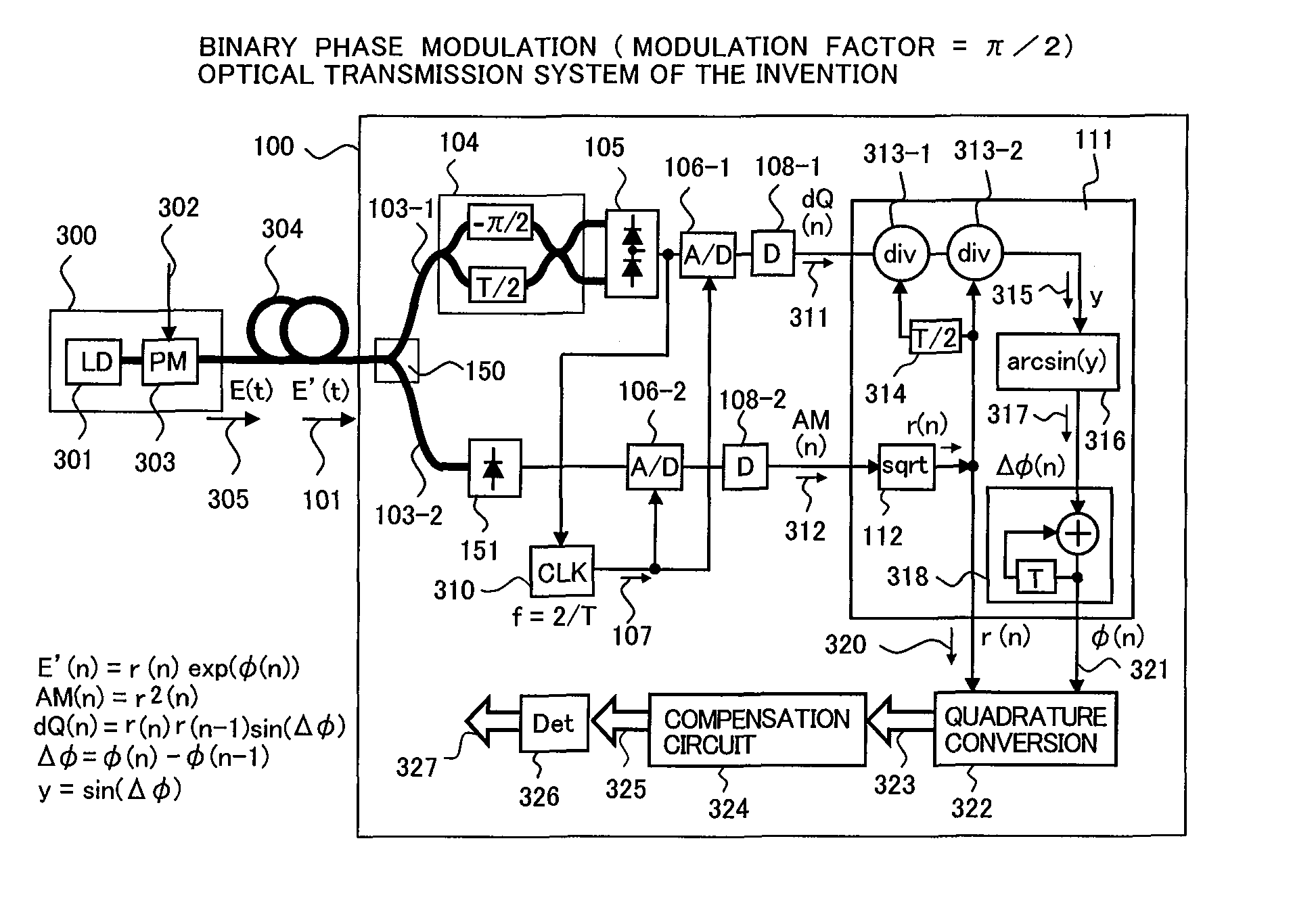
[0064]FIG. 4 shows an optical field receiver 100 according to the present invention and an optical transmission system of the first embodiment using the optical field receiver. FIG. 4(A) is a view showing a configuration of the optical transmission system, wherein optical signal paths are shown by a thick line and electrical signal paths are shown by a thin line.

[0065]In the first embodiment, an optical transmitter 300 is a transmitter of binary phase modulation light. An unmodulated laser beam output from a laser 301 is input to an optical phase modulator 303 to perform phase modulation by applying a binary digital information signal 302 whose symbol rate is R to a modulation terminal of the optical phase modulator, and output from as a transmission optical signal 305 (optical field E(n)). The phase modulation is carried out so that a phase angle θ between signal points corresponding to a mark and a space of the information signal becomes equal to π / 2, as shown in a signal constell...

second embodiment

[0099]FIG. 7 shows an optical field receiver 100 according to the present invention and an optical transmission system of the second embodiment using the optical field receiver.

[0100]In the second embodiment, the optical transmitter 300 generates a binary intensity modulated light as a transmission optical signal 305 by applying the binary digital information signal 302 to the optical-intensity modulator 329. In the optical field receiver of the present invention, because the reconstruction of optical field becomes difficult when the optical signal intensity is about 0, the extinction ratio of the optical signal in the transmission optical signal 305 is previously degraded intentionally so as to be 0.1 to 0.3

[0101]The input optical signal 101 having been input to the optical field receiver 100 is branched into two ways by the optical branching circuit 150, in similar to the first embodiment. One of the branched optical signals is converted into an electrical signal by the optical de...

third embodiment

[0121]FIG. 10(A) shows the optical field receiver 100 according to the present invention and an optical transmission system of the third embodiment using the optical field receiver. In the third embodiment, a quaternary optical amplitude and phase modulator is used as the optical transmitter 300. For example, two groups of binary digital information signals 302-1 and 302-2 are input to an optical intensity modulator 329 and the optical phase modulator 309, respectively, so that a transmission optical signal 305 of the quaternary amplitude and phase modulation is generated by modulating the intensity and phase into two-levels, respectively.

[0122]FIG. 10(B) shows an example of the signal constellation of quaternary amplitude and phase modulated light. In applying to the present invention, the maximum phase transition θ between signal points is preferable to be limited to a predetermined value or less, in similar to the above-mentioned embodiments. In the case of measuring the phase of...


PUM


Abstract

An optical field receiver comprises an optical brancher that branches a received optical multilevel signal into first and second optical signals; an optical delayed detector that performs delayed detection on the first optical signal by a delayed detector with a delay time of T / 2 (where T is equal to a symbol time) and a phase difference of 90 degrees; a balanced optical receiver that converts the optical signal outputted from the first delay detector to an electric signal; and an optical intensity receiver that converts the second optical signal to an electric signal; and an electric field calculating part that generates, from the output signals of the first and second optical receivers, first and second reproduced signals indicative of the phase angle and amplitude value of the received symbol represented by the complex signal in each symbol time T.

Description

TECHNICAL FIELD[0001]The present invention relates to an optical information transmission technology, and more specifically, to an optical field receiver suitable for receiving an optical multilevel signal transmitted over an optical fiber, an optical multilevel signal receiver, and an optical transmission system.BACKGROUND ART[0002]In recent years, even though the quantity of information (transmission capacity) transmittable over one optical fiber continues to increase as the number of multiplexed wavelength channels increases and the modulation speed of an optical signal becomes faster and faster. The increase of the transmission capacity reaches a limit of approximately 10 T (Tera)bit / s. The main reason why it is difficult to increase the transmission capacity is that a wavelength bandwidth usable for the optical transmission reaches the maximum bandwidth of a wavelength bandwidth (a sum of C-band, L-band, and S-band corresponds to approximately 80 nm=10 THz) of an optical fiber ...

Claims


Application Information

Patent Timeline
Patent Type & Authority Patents(United States)
IPC IPC(8): H04B10/06H04B10/2513H04B10/40H04B10/50H04B10/516H04B10/556H04B10/58H04B10/60H04B10/61H04B10/67H04B10/69H04L27/34
CPCH04B10/61H04B10/611H04B10/613H04L27/223H04B10/6163H04L25/03057H04B10/6161H04B10/65
Inventor KIKUCHI, NOBUHIKO
Owner HITACHI LTD
Why Eureka
Try Eureka