
Power management in low power wireless link

a low-power wireless link and power management technology, applied in power management, loudspeaker spatial/construction arrangement, transmission, etc., can solve the problems of waste of power by devices with overhead current in a particular setup, and achieve the effect of influencing the speed of power level adjustment, reducing the effect of power level change, and large intended power level changes

Active Publication Date: 2012-05-29
OTICON
View PDF27 Cites 11 Cited by
  • Summary
  • Abstract
  • Description
  • Claims
  • Application Information

AI Technical Summary

Benefits of technology

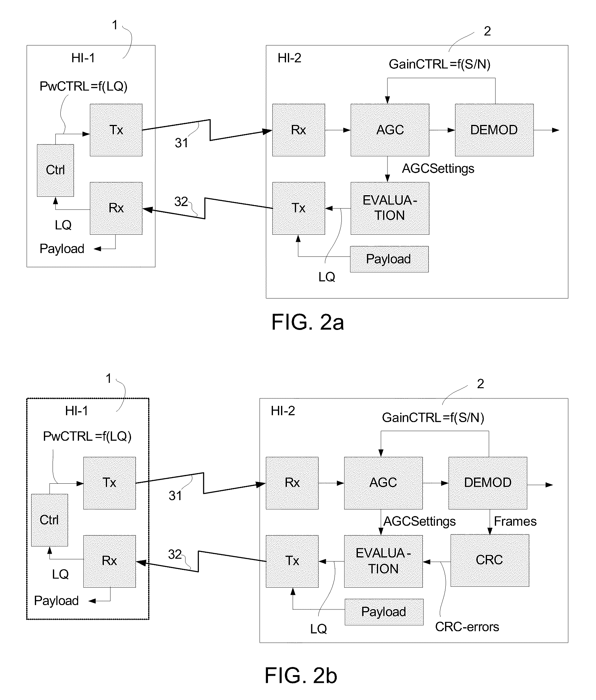
The present invention relates to a communication system that controls power consumption in a short range wireless link. The system includes two communication devices, each with transmit and receive units for establishing a wireless link. The first device dynamically adjusts the transmit power based on the quality of the link, while the second device has a control unit for adjusting the transmit power based on the quality of the link. This allows for a partial power-down mode of the system when the two devices are not in normal use. The system can be used in portable devices with limited battery power, such as hearing instruments or mobile phones, and can be adapted to different needs and circumstances. The measure of the quality of the link can be extracted based on the signal received from the transmitting device or the receiving device. The system can use different types of wireless links, such as near-field or far-field communication, and can be based on various modulation schemes. The invention enables efficient use of power in wireless communication devices and provides a better user experience.

Problems solved by technology

The overhead in current in a particular setup represents a waste of power for those devices.

Method used


Image

  • Power management in low power wireless link
  • Power management in low power wireless link
  • Power management in low power wireless link

Examples


Embodiment Construction

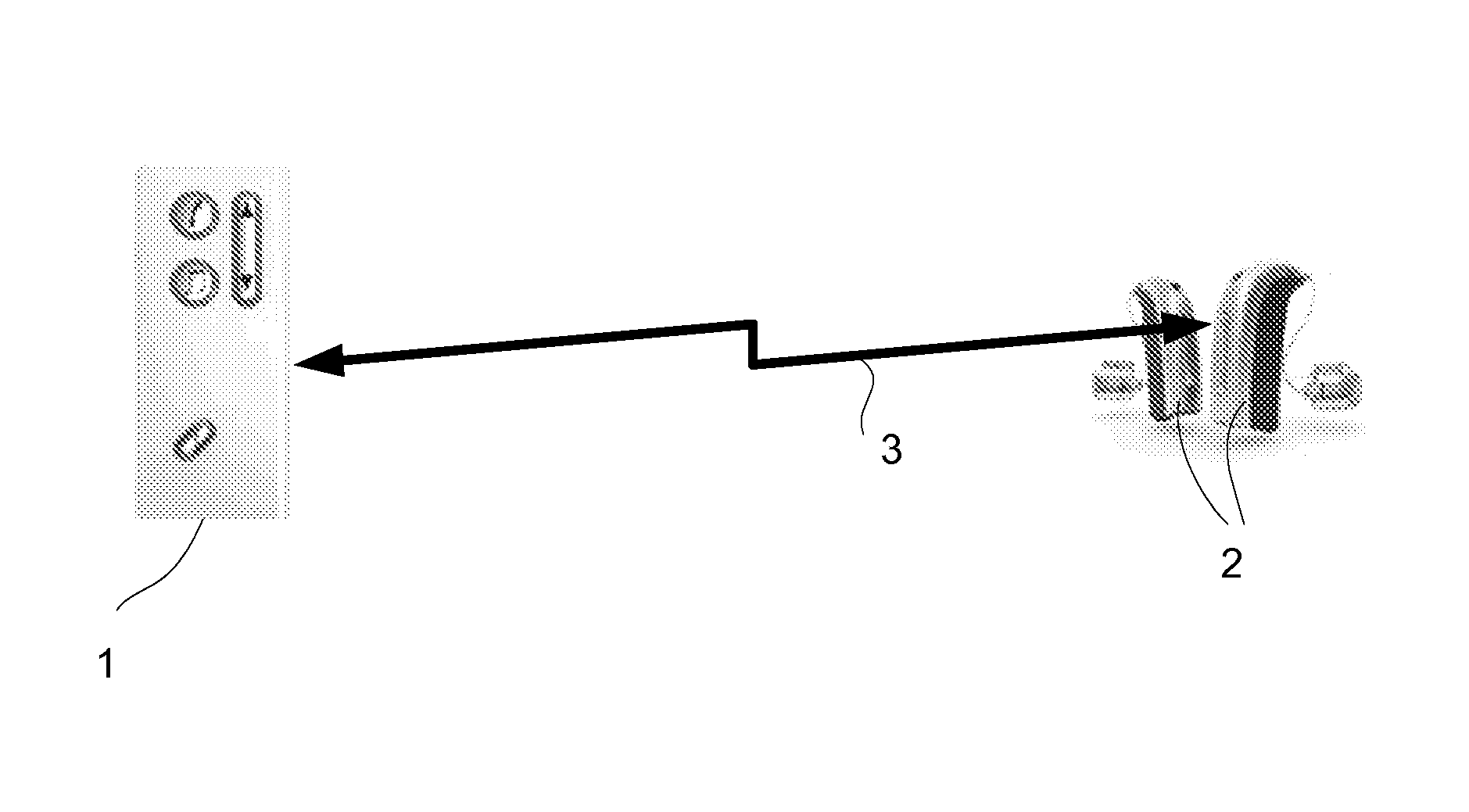
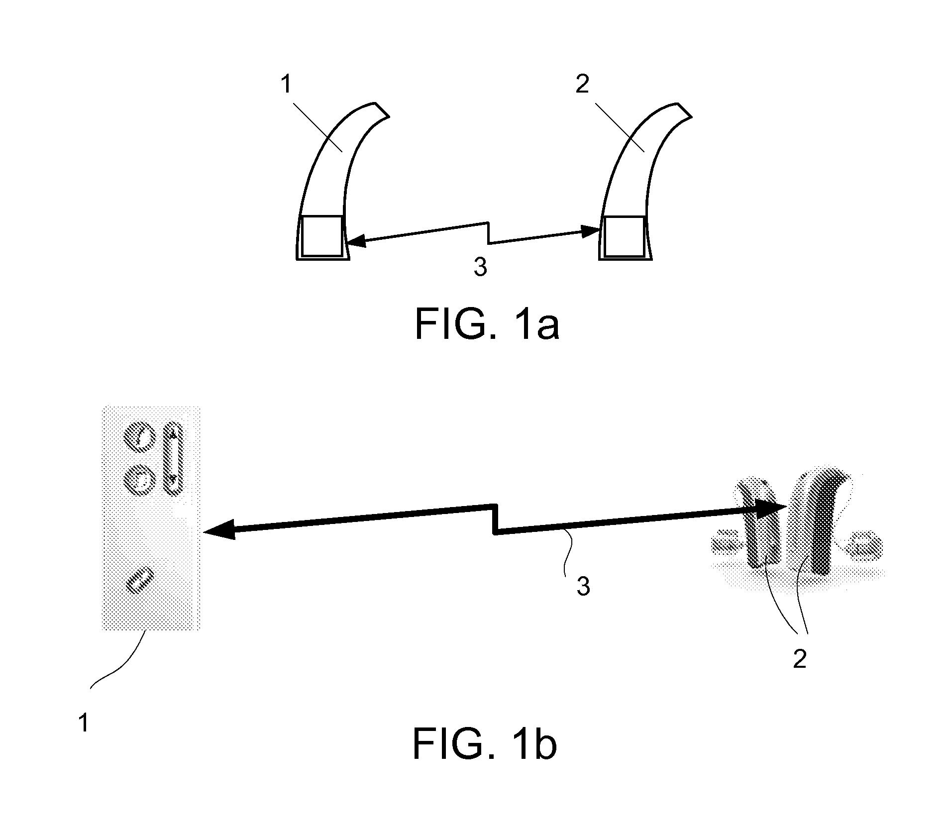
[0078]FIG. 1 generally illustrates a wireless link 3 between first and second communication devices 1, 2. Applications of the present invention include the wireless communication between two body-worn, low power communication devices, e.g. two hearing instruments (cf. e.g. FIG. 1a) or between an audio selection device (audio gateway) and one or more hearing instruments (cf. e.g. FIG. 1b). Alternatively, the communication devices 1, 2 could be a pair of headphones, a pair of hearing protective ear plugs, a mobile telephone and a listening device, an entertainment device (e.g. a music player) and a listening device, etc.

[0079]In the following (FIG. 1a), an embodiment of the invention is exemplified by a binaural hearing aid system comprising two hearing instruments adapted to be worn at and / or in each ear of a user, the hearing instruments having a wireless link between them for exchanging control or status information (and possibly audio signals) between them. In an embodiment, no au...


PUM


Abstract

The invention relates to a communication system comprising a first and a second communication device, each comprising transmit and receive units for establishing a wireless link between the devices, wherein the first device is a portable listening device. The invention further relates to a method, a data processing system and a medium. The object of the present invention is to control power consumption in a short range wireless link. The problem is solved in that at least the first communication device comprises a control unit for dynamically adjusting the transmit power of its transmit unit based on a measure of the quality of the link, wherein the system is adapted to use the dynamic transmit power regulation to implement a partial power-down mode of the system, when the two communication devices are expected NOT to be in a normal use, wherein the partial power-down mode at least comprises a power-down of the components related to the wireless link. This has the advantage of enabling an adaptation of the power consumption to the current needs. The invention may e.g. be used for wireless communication between (portable) low power devices, e.g. between a pair of hearing instruments.

Description

TECHNICAL FIELD[0001]The present invention relates to low power wireless communication, and especially to power management, including power regulation. The invention relates specifically to a communication system comprising a first and a second communication device, each comprising transmit and receive units for establishing a wireless link between the devices.[0002]The invention furthermore relates to a method of controlling power consumption in a wireless link between two communication devices.[0003]The invention furthermore relates to a data processing system and to a tangible computer-readable medium.[0004]The invention may e.g. be useful in applications such as wireless communication between (portable) low power devices, e.g. between a pair of hearing instruments.BACKGROUND ART[0005]First generation wireless link systems for portable listening devices, such as hearing aids, have typically been based on fixed transmitted power between the devices. The transmitter current is, e.g...

Claims


Application Information

Patent Timeline
Patent Type & Authority Patents(United States)
IPC IPC(8): H04B7/00
CPCH04R25/552H04R25/70H04W52/52H04W52/245H04W52/265H04W52/10H03F2200/451
Inventor LERKE, PETER DAM
Owner OTICON
Learn More