Method for simulating performance of golf club head

a golf club head and performance simulation technology, applied in the field of golf club head simulation, can solve the problems of difficult to set the shell element on the recent club head model, and increasing the number of finite elements, and achieve the effect of short calculation time and high accuracy

Inactive Publication Date: 2012-05-29
BRIDGESTONE SPORTS
View PDF14 Cites 6 Cited by
  • Summary
  • Abstract
  • Description
  • Claims
  • Application Information

AI Technical Summary

Benefits of technology

[0010]The invention was made in view of these problems and provides a method for simulating performance of a golf club head, which can obtain calculation results with high accuracy within a short calculation time by utilizing an optimal modeling method in finite element modeling when attempting to perform a simulation analysis on a golf club head using the finite element method.
[0012]Since the shell elements are used as the finite elements, the number of finite elements, which form a model, is reduced. Furthermore, since the shell elements are arranged on the surface of the model of the golf club head, the accuracy of simulation can be increased greatly.
[0014]Since the shell elements and the other elements are combined appropriately as required, a simulation result with better accuracy can be obtained.
[0016]Accordingly, a simulation result with much better accuracy can be realized.
[0019]According to the method for simulating performance of a golf club head set forth above, when a simulation analysis is carried out on a golf club head using the finite element method, since the optimal modeling method in modeling finite elements is used, it is possible to obtain calculation results with high accuracy within a short calculation time.

Problems solved by technology

However, it has been difficult to set the shell element on recent club head models, which have faces and bodies part of which is different in thickness from the other part.
This is because since the position of the shell element on the neutral plane has to be changed depending on models having different thicknesses, the number of position settings of shell elements on neutral planes is increased remarkably, which leads to drawback that calculation time for a simulation becomes long.
In addition, in a case where the thickness of a model varies, while solid elements are often used as the finite element, the number of finite elements increases inevitably, which leads to drawback that calculation time for a simulation becomes longer as the number of finite elements increases.
Furthermore, in the case of the solid element, there arises a problem that the simulation accuracy gets worse in comparison with the shell element.

Method used


Image

  • Method for simulating performance of golf club head
  • Method for simulating performance of golf club head
  • Method for simulating performance of golf club head

Examples


first example

FIGS. 2 and 3

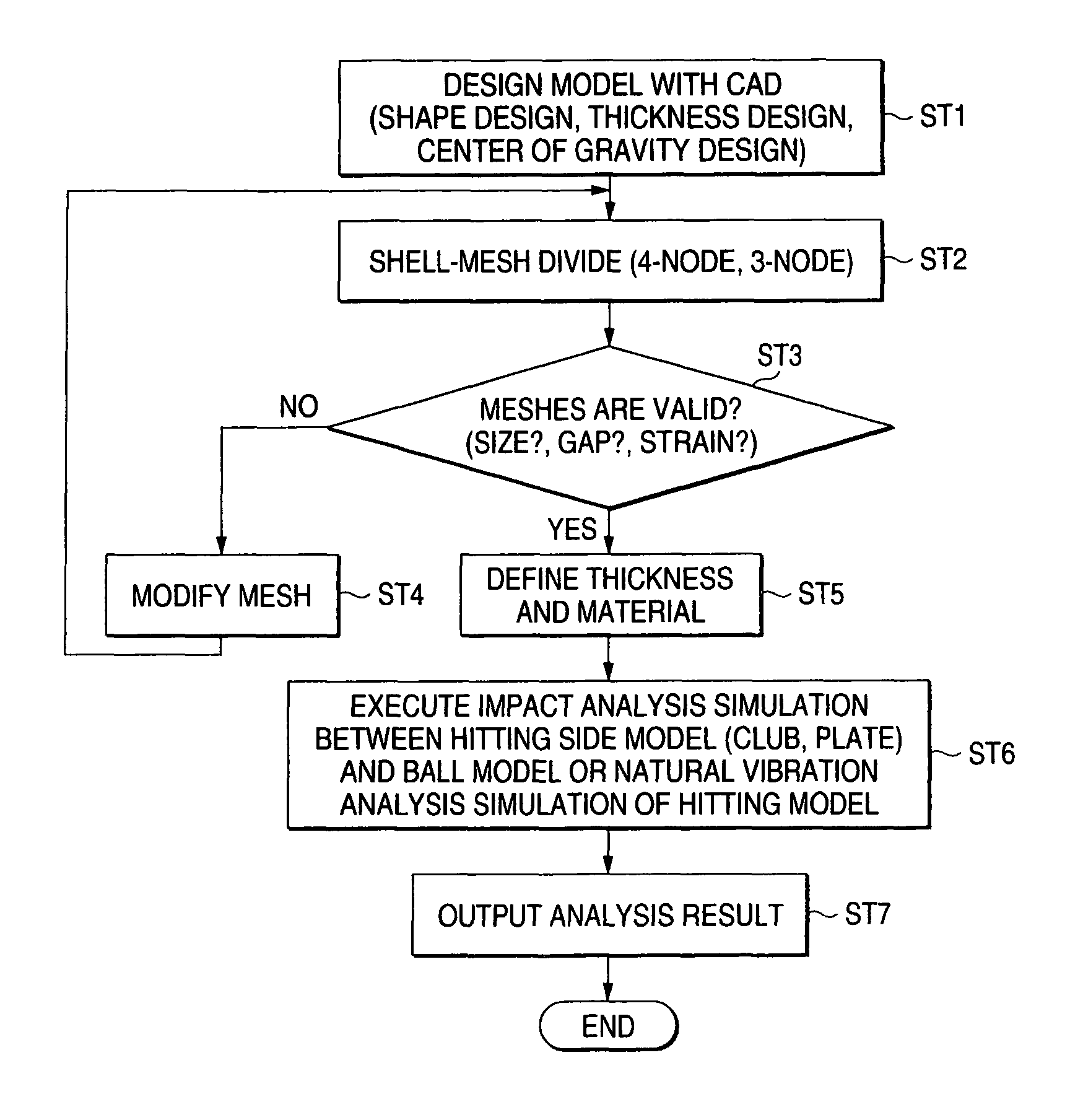
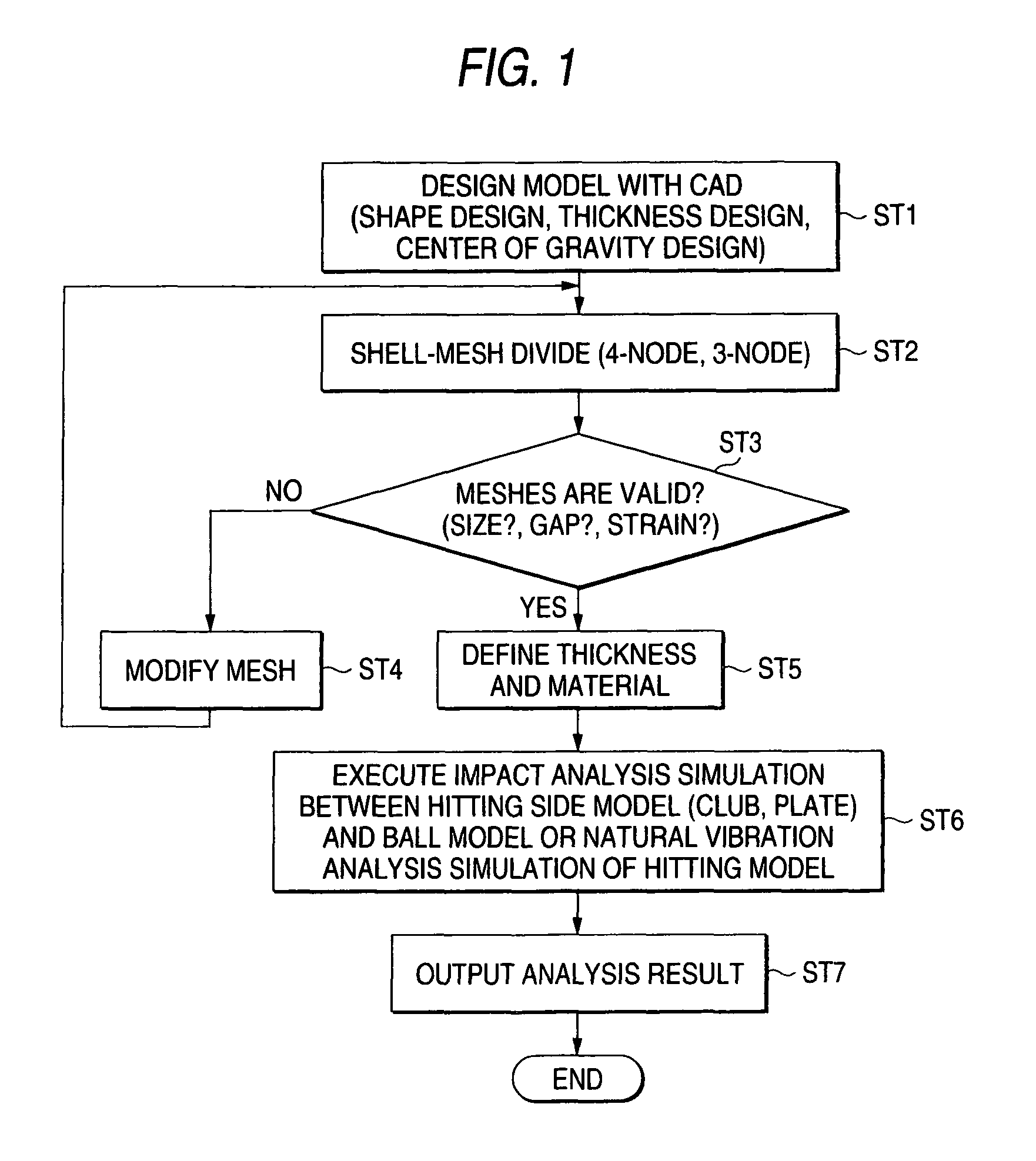
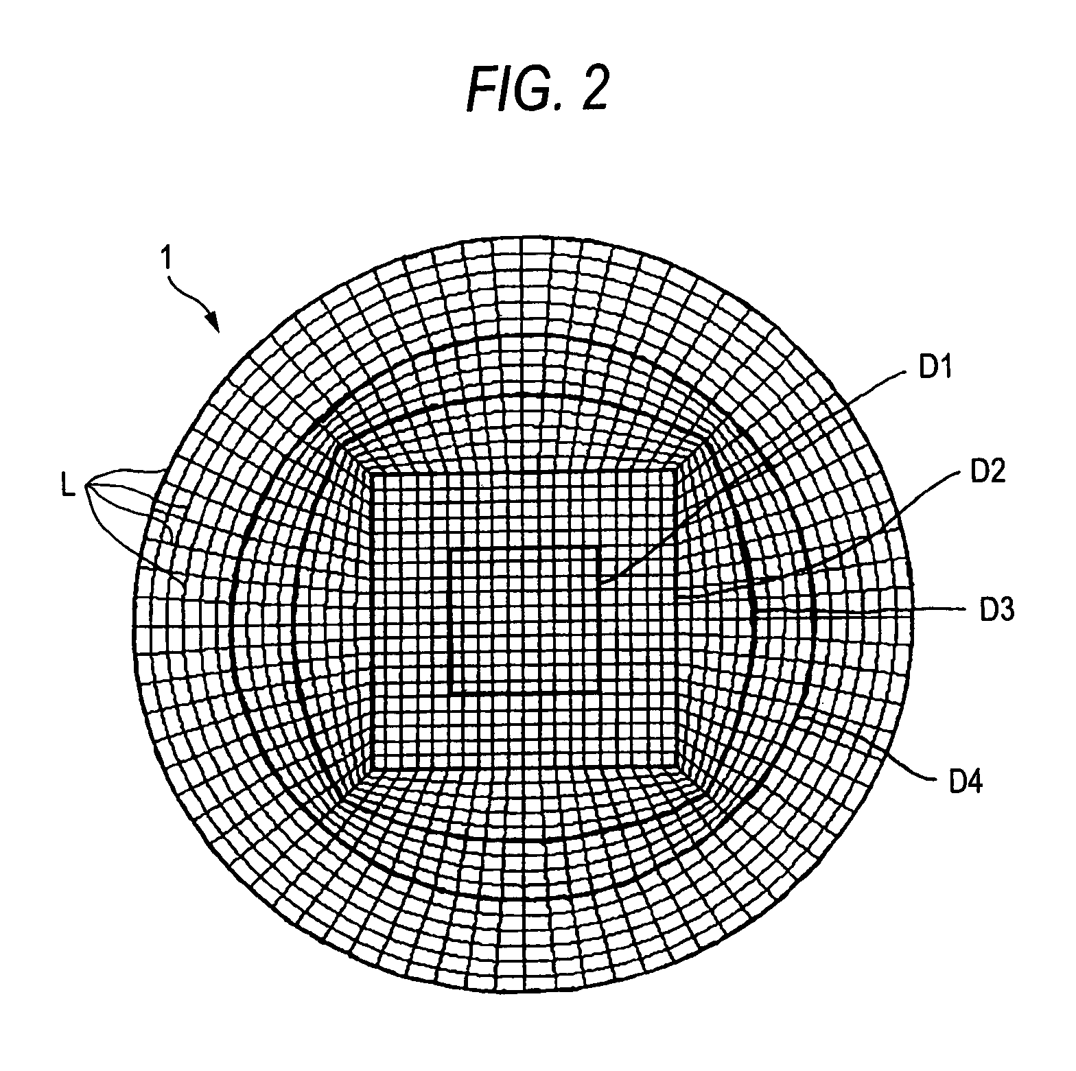
[0035]In a first example, this embodiment of the invention is applied to a case where a plate model having, as shown in FIG. 2, a circular shape on a front side is used as a hitting model.

[0036]This plate model 1 is assumed to be used for a hitting surface of a golf club head. Mesh portions, which are divided up by innumerable fine dividing lines L, L in FIG. 2, are units of models to which the shell elements are applied. Then, the plate model 1 is divided into five annular areas from a central portion toward an outside thereof as shown by thick annular boundary lines D1 to D4. The plate model 1 is formed so that the thickness increases from the central portion to the outside thereof.

1) Number of Mesh Elements (Number of Finite Elements)

[0037]When the plate model 1 that is formed as has been described above was divided into models using four-node shell elements according to the method of this embodiment, the number of mesh elements (the number of finite elements) was 1,...

second example

FIG. 4

[0044]As shown in FIG. 4, a second example is applied to a wood model 2, which is the hitting side model.

[0045]In this wood model 2, mesh portions divided up by innumerable fine dividing lines L1, L1 shown in FIG. 4 are units of models to which shell elements are applied.

1) Number of Mesh Elements (Number of Finite Elements)

[0046]When the wood model 2 that is formed as has been described above was divided into models using four-node shell elements based on the method of this embodiment, the number of mesh elements (the number of finite elements) was 1,624. In this case, vector directions of the shell elements, which were applied to the respective mesh elements, were identical to each other. Shapes of the respective models (mesh elements) to which the shell elements were applied were identical to the counter shape of the wood model 2, which constitutes a shape to be required.

[0047]On the other hand, when the wood model 2 was divided into models using the solid elements (which w...


PUM


Abstract

A method for simulating performance of a golf club head includes dividing a model of the golf club head of a hollow structure using shell elements, and arranging the shell elements on a surface of the model of the golf club head.

Description

[0001]This application is based upon and claims the benefit of priority from the prior Japanese Patent Application No. 2004-379320 filed on Dec. 28, 2004, the entire contents of which are incorporated herein by reference.BACKGROUND OF THE INVENTION[0002]1. Field of the Invention[0003]The invention relates to a method for simulating performance of a golf club head, and more particularly to a method for simulating performance of a golf club head, which is suitable for analyzing the performance of the golf club head using the finite element method (FEM).[0004]2. Description of the Related Art[0005]Recently, in designing golf clubs, various types of performances of golf club heads are simulated using to use a general-purpose computer.[0006]For example, US 20040162158 A discloses designing golf club heads and golf balls using the finite element method by applying finite element models as golf club head models and golf ball models. Specifically, the thickness, material, weight and shape o...

Claims


Application Information

Patent Timeline
Patent Type & Authority Patents(United States)
IPC IPC(8): G06G7/48A63B53/00A63B53/04A63B102/32G06F17/50
CPCG06F17/5018G06T17/20A63B53/04A63B53/0466A63B59/0074A63B2059/0003A63B60/42G06F30/23A63B60/002A63B60/46
Inventor MATSUNAGA, HIDEO
Owner BRIDGESTONE SPORTS
Why Eureka
Try Eureka