
Wire tube structure for exhaust component

a technology of exhaust components and wire tubes, applied in the direction of pipe elements, mechanical equipment, machines/engines, etc., can solve the problems of fiber material filling, disadvantageous weight and cost perspective, etc., and achieve the effect of reducing noise configuration

Active Publication Date: 2012-06-05
EMCON TECHNOLOGIES
View PDF13 Cites 1 Cited by
  • Summary
  • Abstract
  • Description
  • Claims
  • Application Information

AI Technical Summary

Benefits of technology

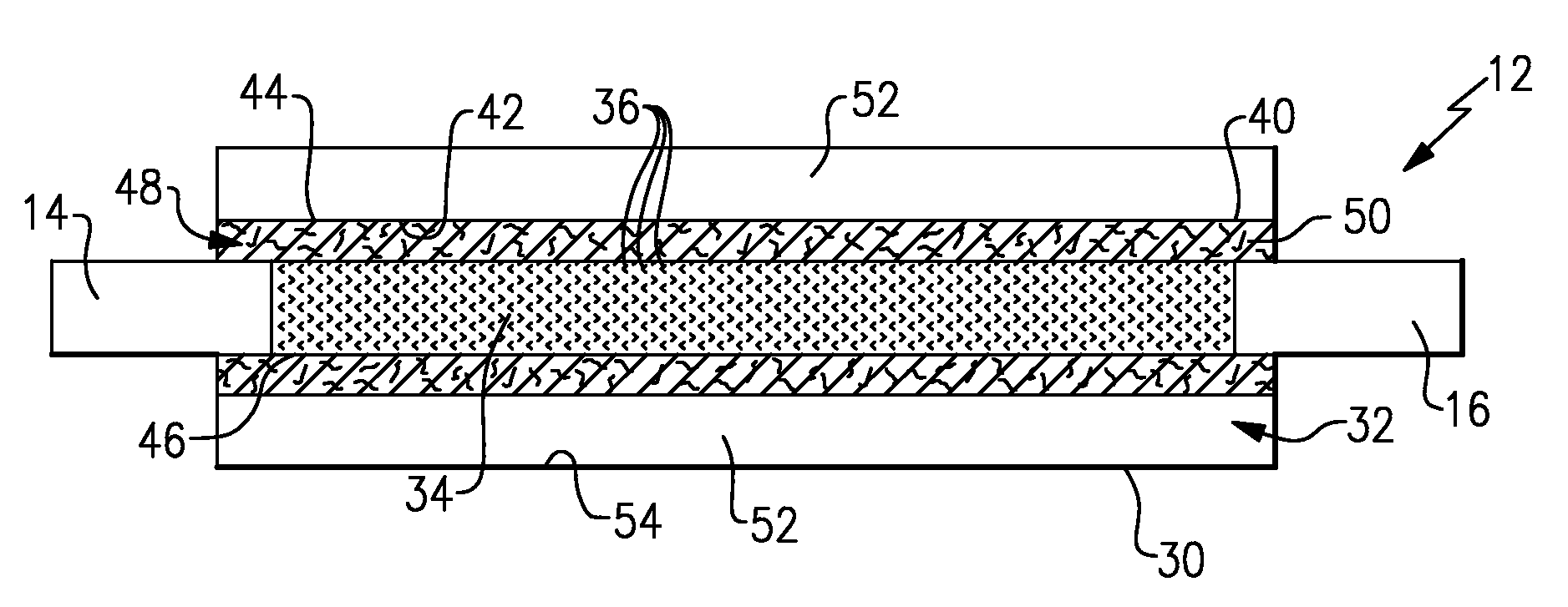
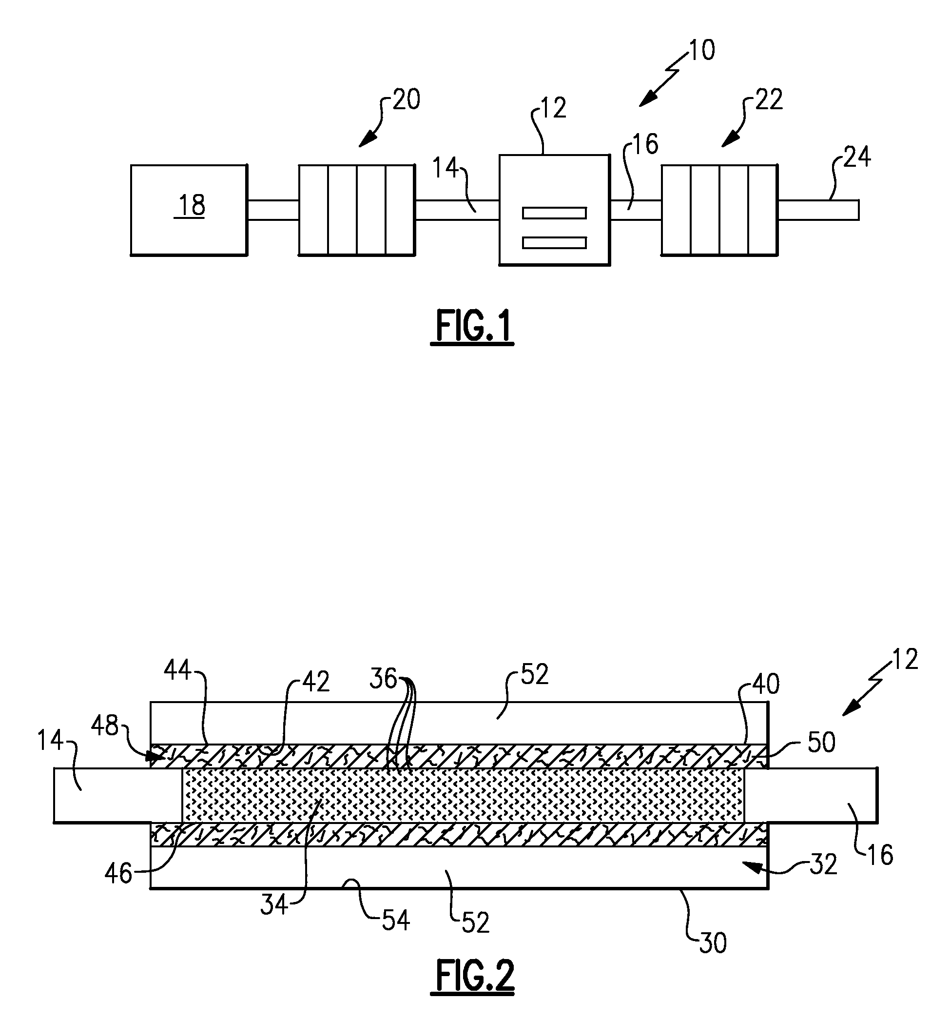
[0004]A vehicle exhaust component includes an internal pipe surrounded by a tube structure. The tube structure is radially spaced from the internal pipe by a gap to define an optimum location for fiber material. The gap is substantially filled with the fiber material to provide a reduced noise configuration without requiring the entire internal cavity to be filled with fiber material.
[0005]In one example, the tube structure is comprises a wire tube. The wire tube is made of a wire mesh or knitted wire material. The wire tube surrounds a substantial length of the internal pipe. Thus, the fiber material, which is located in the gap to directly surround a substantial length of the internal pipe, is positioned at an optimum location without adversely affecting weight and cost.

Problems solved by technology

One common problem with exhaust system components, such as a muffler for example, is that the fiber material must fill an entire muffler inner cavity in order to be located around the internal pipes.
This is disadvantageous from a weight and cost perspective.

Method used


Image

  • Wire tube structure for exhaust component
  • Wire tube structure for exhaust component

Examples


Embodiment Construction

[0009]As shown in FIG. 1, an exhaust system 10 includes an exhaust component 12 having an exhaust gas inlet pipe 14 and an exhaust gas outlet pipe 16. Exhaust gases generated by an engine 18 are communicated through the exhaust component 12 from the exhaust gas inlet pipe 14 to the exhaust gas outlet pipe 16. One or more exhaust components, generally referred to at 20 can be positioned between the exhaust component 12 and the engine 18. Further, additional exhaust components 22 may be located downstream of the exhaust component 12. Exhaust gases exit the exhaust system 10 through at least one tailpipe 24.

[0010]In one example, the exhaust component 12 comprises a muffler. As shown in FIG. 2, the exhaust component 12 includes an outer shell 30 defining an internal cavity 32. At least one internal pipe 34 is positioned within the internal cavity 32. This internal pipe 34 can be positioned anywhere within the internal cavity 32. In the example shown, the internal pipe 34 includes perfor...


PUM

PropertyMeasurementUnit
lengthaaaaaaaaaa
areaaaaaaaaaaa
noiseaaaaaaaaaa

Abstract

A vehicle exhaust component includes an outer shell defining an internal cavity and at least one internal pipe located within the internal cavity. A wire tube surrounds the internal pipe and is spaced apart from the pipe by a radial gap. This radial gap is filled with a fiber material.

Description

TECHNICAL FIELD[0001]The subject invention relates to a wire tube structure used in a vehicle exhaust system, and more particularly relates to a wire tube structure that is configured to locate fiber material at optimum locations within an exhaust component.BACKGROUND OF THE INVENTION[0002]Exhaust systems are widely known and used with combustion engines. Typically, an exhaust system includes exhaust tubes that convey hot exhaust gases from the engine to other exhaust system components, such as mufflers, resonators, etc. Mufflers and resonators include acoustic chambers that cancel out sound waves carried by the exhaust gases. Each component includes at least one inlet pipe and at least one outlet pipe, and can include one or more internal tubes or pipes within the component to direct exhaust gas flow from the inlet pipe to the outlet pipe.[0003]These exhaust components often include fiber material, such as Basalt or Fiberglass materials for example, that act to further reduce noise...

Claims


Application Information

Patent Timeline
Patent Type & Authority Patents(United States)
IPC IPC(8): F16L9/14
CPCF01N1/003F01N1/006F01N1/24F01N13/16F16L9/21F16L55/0336Y10T29/49398F01N2450/06F01N2310/14
Inventor CALLAHAN, JOSEPH E.ABRAM, KWIN
Owner EMCON TECHNOLOGIES
Learn More