Optical absorption gas sensor

a technology of optical absorption and gas sensor, which is applied in the field of optical absorption gas sensor, can solve the problems of small manufacturing errors that can have a significant adverse effect on the amount of light reaching the detector, particularly acute problems, and special concerns, and achieve good performan

Active Publication Date: 2012-06-05
ALPHASENSE LTD
View PDF18 Cites 10 Cited by
  • Summary
  • Abstract
  • Description
  • Claims
  • Application Information

AI Technical Summary

Benefits of technology

[0025]Preferably, the detector is in the form of a generally flat body (such as a disc) which extends obliquely from the inner wall of the body of the sensor into the chamber (i.e. not radially when the chamber is generally circular, nor directly towards the centre of the chamber where the chamber is not circular) such that the volume within the chamber on the first side of the detector is less than the volume within the chamber on the second side of the detector. In combination with the use of two or more reflectors which reduce the divergence of the light beam, and which are configured such that light falling on the detector is predominantly convergent, this allows a collector (see below) with a larger internal reflective surface area to be provided than would be the case if the planar detector extended inwards along a radius of the chamber and bisected part of the chamber. This allows a larger collector to be provided which better controls the spatial and angular distribution of light from the light-source which is directed onto the first reflector.
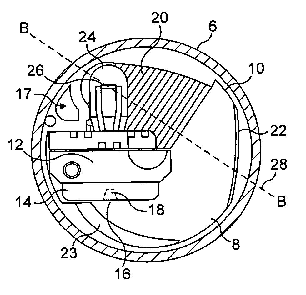
[0030]This has the effect that, to a first order of approximation, light which is emitted by the light source in the region of the centre of the part-spherical portion, will be reflected by the portion of the interior of a sphere and the reflected light will form a mirror image of the light source. This reduces the sensitivity of the amount of light falling on the detector to the precise location of the light source. This increases tolerance to manufacturing imperfections, particularly those imperfections resulting in the light source not being coincident with the centre of the sphere portion, and also increases tolerance to movement of the light source in use. This is particularly relevant where the light source is the filament of an incandescent lamp which may move in use due to thermal expansion, vibration, shocks etc. This is especially relevant in embodiments of the sensor in which the optics are symmetric about a plane of symmetry, which is discussed further below. The use of a sphere portion is especially beneficial when the size of the light source is significant compared to the size of the collector, e.g. where the light source extends across more than 10% of the width of the collector in a plane which bifurcates the light source.
[0033]This allows the light source to be located further from the first reflector than would be the case if the light-emitting device extended into the collector towards the first reflector. This increases the average path length from the light source to the detector.
[0036]The light-source may be elongate, for example, the light-source may be an elongate filament of an incandescent bulb. The elongate light-source may be parallel to the length of the light-emitting device. The elongate light-source may be orthogonal to the length of the light-emitting device. The elongate light-source may be other than parallel to the axis of the collector. In embodiments with a plane of symmetry (discussed below) the elongate light-source may be other than symmetric about the plane of symmetry. This will occur if, as is common with the filament of incandescent bulbs, the filament is orthogonal to the length of the incandescent bulb and the incandescent bulb extends into the collector towards the rear of the collector. In this case, where the interior surface of the collector comprises part of the interior surface of a sphere, this has the effect of, to a first order of approximation, avoiding an asymmetry in the distribution of light about the plane of symmetry.
[0043]Preferably, the light source is centred on the plane of symmetry. Preferably, the light source is part of an elongate light-emitting device which extends into the collector in the plane of symmetry. Where the light-emitting device extends into the collector through an aperture in the reflective inner surface of the collector, this has the effect of distorting the pattern of reflection of light in comparison to an uninterrupted collector. However, where the measurement and reference detectors are located symmetrically on either side of the plane of symmetry and the light-emitting device extends into the collector in the plane of symmetry, the distortion does not affect the relative amount of light which reaches the measurement and reference detectors, nor the average path length of light which reaches the measurement and reference detectors. In this case, the light-emitting device will typically be symmetrical on either side of the plane of symmetry.
[0044]Either or both of the first and second reflectors are preferably concave in a plane which is orthogonal to the plane of symmetry and symmetric about the plane of symmetry. The collector and the first reflector are preferably configured such that the distribution of light reflected from the surface of the first reflector is bifurcated. Where the detector comprises separate measurement and reference detectors located symmetrically on either side of the plane of symmetry, the collector and reflectors are preferably configured such that the distribution of light which reaches the detector is bifurcated so that the intensity of light which falls on each of the measurement and reference detectors is greater than the intensity of light which is incident on the detector in the plane of symmetry between the measurement and reference electrodes. This enables a larger proportion of the light from the light source to reach the measurement and reference detectors than would be the case if the distribution of light which reaches the detectors was more intense in the plane of symmetry than at each of the measurement and reference detectors.

Problems solved by technology

A disadvantage of sensors in which light is reflected many times is that small manufacturing errors can have a significant adverse effect on the amount of light reaching the detector.
These problems are particularly acute for sensors which comprise separate measurement and reference light detectors.
In this case, errors which affect the relative amount of light which reaches the measurement and reference light detectors, or which affect the relative distribution of path lengths of light reaching the measurement and reference detectors, are of particular concern.
These issues are particularly critical in sensors which must occupy small volumes.
This is a confined volume which presents a significant engineering challenge.

Method used


Image

  • Optical absorption gas sensor
  • Optical absorption gas sensor
  • Optical absorption gas sensor

Examples


Embodiment Construction

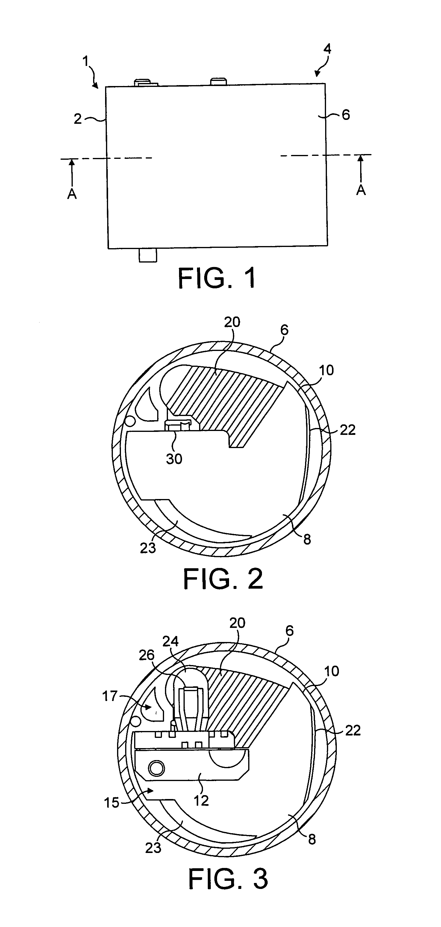
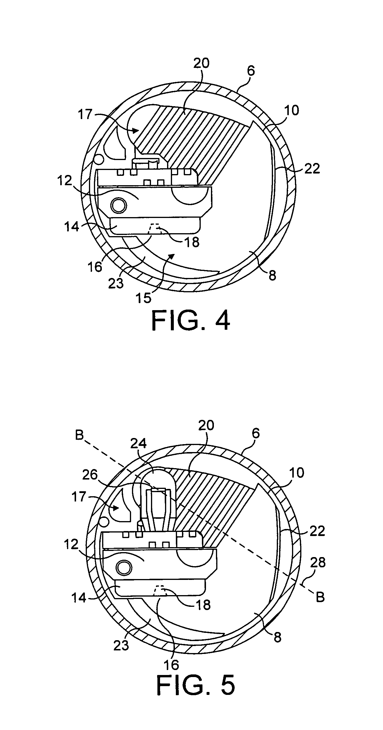
[0064]FIG. 1 is a side view of an optical absorption gas sensor 1 having a body 2, which is generally in the shape of a right circular cylinder, a top surface 4 and cylindrical outer wall 6. FIG. 2 is a cross-section of the sensor through plane A-A viewed in an upwards direction, omitting the detector assembly (including the detector) and the incandescent lamp. FIG. 3 is a corresponding cross-section, omitting only the detector. FIG. 4 is a corresponding cross-section, omitting the incandescent lamp, and FIG. 5 is a corresponding cross-section which includes all components.

[0065]The sensor comprises an internal chamber 8 (which is also generally in the form of a right circular cylinder), defined by the inner wall 10 of the sensor body. A detector assembly 12 extends from the inner wall of the sensor into the chamber and supports a detector 14 in the form of a disc with a planar first surface 16, which is attached to a first side of the detector assembly. The detector assembly and se...


PUM


Abstract

An optical absorption gas sensor comprising a body having an internal wall which defines a chamber, at least one aperture in the body through which a gas sample can enter the chamber, a light source, at least one reflector, a detector assembly which extends into the chamber and has a first side and an opposite second side, a detector which measures light which is incident at least a range of angles on at least a part of a first surface of the detector assembly on the first side of the detector assembly, wherein the light source is located within the chamber on the second side of the detector assembly, the whole being configured such that light from the light source passes through the gas sample and is reflected around the detector assembly, by the at least one reflector, onto the detector.

Description

[0001]This application claims priority to UK Patent Application No. 0705356A filed 21 Mar. 2007, the entire contents of which are hereby incorporated by reference.FIELD OF THE INVENTION[0002]The invention relates to the field of optical sensors, particularly optical absorption gas sensors.BACKGROUND TO THE INVENTION[0003]Optical absorption gas sensors determine the concentration of a gaseous analyte in a gas sample by measuring the attenuation of light passing through the gas sample due to absorption by the analyte of interest. Many such sensors use light in the infra-red region where gases such as carbon dioxide and methane have absorption lines.[0004]In dispersive infra-red sensors, light of a series of wavelengths which includes one or more absorption lines of the analyte which is to be detected is directed through a gas sample and its intensity is measured by a detector. In non-dispersive infra-red (NDIR) sensors, light of a broad range of wavelengths is passed through a gas sam...

Claims


Application Information

Patent Timeline
Patent Type & Authority Patents(United States)
IPC IPC(8): G01J5/02
CPCG01N21/0303G01N21/3504G01N2021/3166
Inventor HODGKINSON, ELIZABETH JANESAFFELL, JOHN ROBERTSMITH, RICHARD
Owner ALPHASENSE LTD
Why Eureka
Try Eureka