
Bi-directional trimming methods and circuits for a precise band-gap reference

a reference circuit and bi-directional technology, applied in resistor trimming, process and machine control, instruments, etc., can solve the problems of reference voltage overshot without any way to compensate for blown permanent fuse blowing, and difficulty in precisely tuning the resistance valu

Active Publication Date: 2012-06-05
HONG KONG APPLIED SCI & TECH RES INST
View PDF19 Cites 15 Cited by
  • Summary
  • Abstract
  • Description
  • Claims
  • Application Information

AI Technical Summary

Benefits of technology

The bi-directional trimming capability reduces trimming time, improves temperature coefficient stability, and allows for more accurate initial resistance value selection, resulting in a stable and efficient bandgap reference voltage generation.

Problems solved by technology

While trimming is useful, it is difficult to precisely tune the resistance value.
The reference voltage may be overshot without any way to compensate when permanent fuses are blown.

Method used


Image

  • Bi-directional trimming methods and circuits for a precise band-gap reference
  • Bi-directional trimming methods and circuits for a precise band-gap reference
  • Bi-directional trimming methods and circuits for a precise band-gap reference

Examples


Embodiment Construction

[0021]The present invention relates to an improvement in trimable bandgap reference circuits. The following description is presented to enable one of ordinary skill in the art to make and use the invention as provided in the context of a particular application and its requirements. Various modifications to the preferred embodiment will be apparent to those with skill in the art, and the general principles defined herein may be applied to other embodiments. Therefore, the present invention is not intended to be limited to the particular embodiments shown and described, but is to be accorded the widest scope consistent with the principles and novel features herein disclosed.

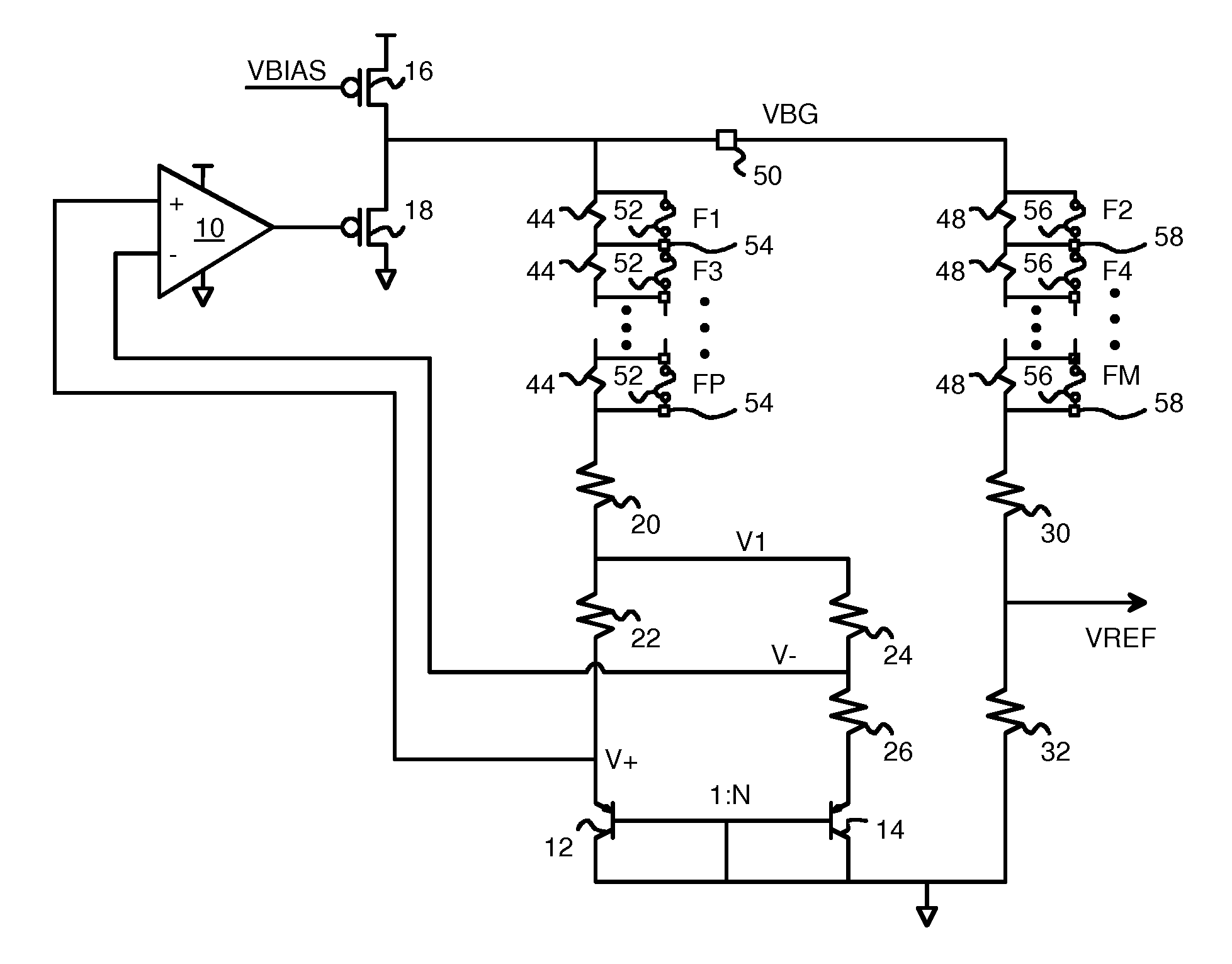
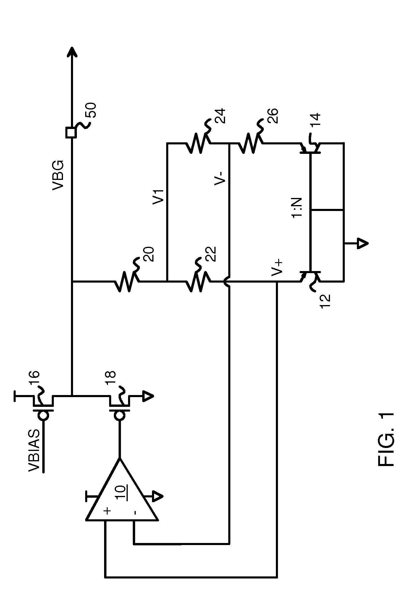
[0022]FIG. 1 is a block diagram of a bandgap reference circuit. PNP transistors 12, 14 have their collectors and their bases tied to ground. PNP transistor 14 is N times larger than PNP transistor 12, and thus sinks about N times more collector current under the same bias conditions.

[0023]A bandgap reference voltag...


PUM


Abstract

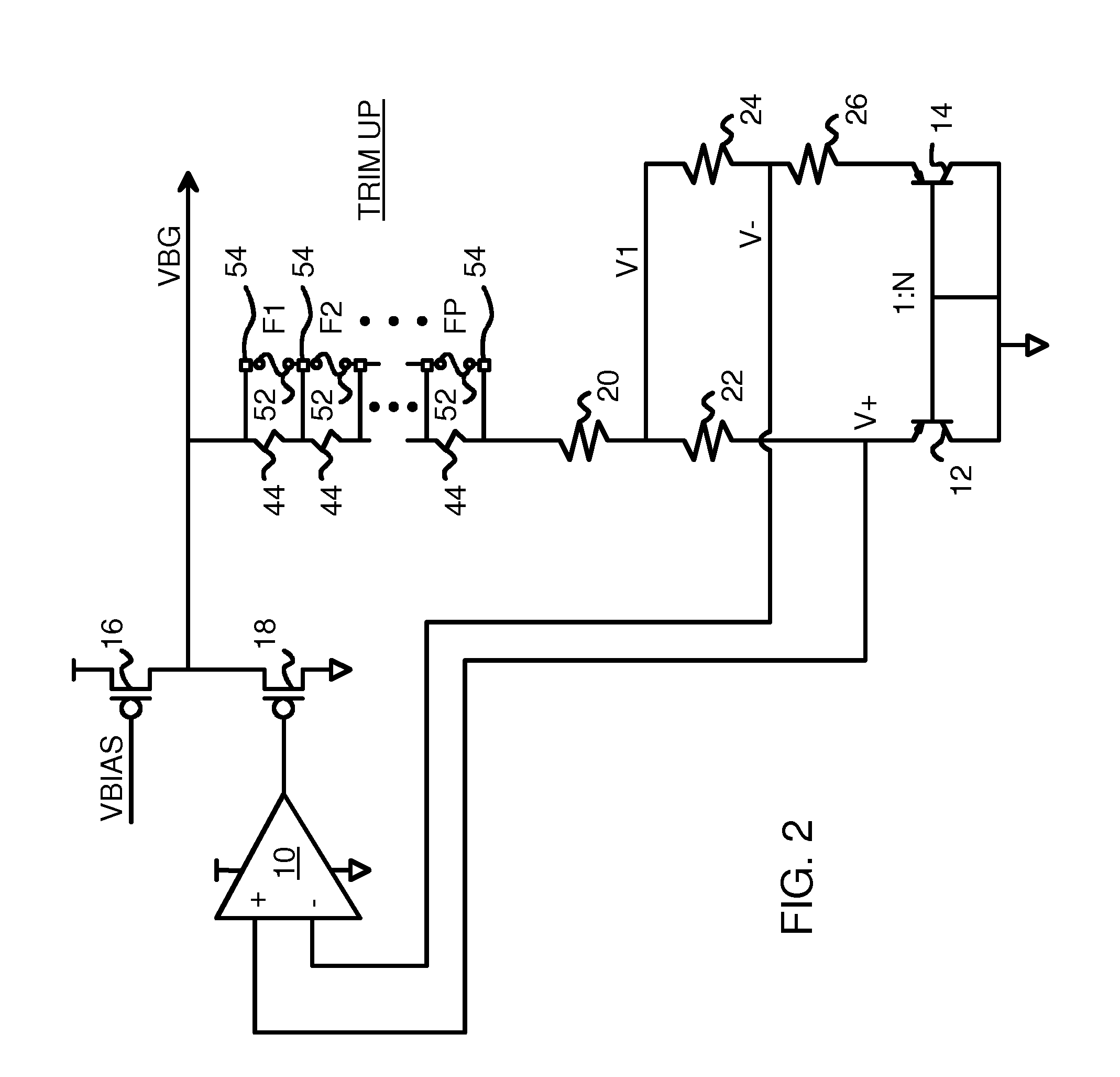
A bandgap reference circuit has trimming-up resistors and trimming-down resistors for bi-directional trimming. PNP transistors have base and collectors grounded and emitters connected to parallel resistors. A difference resistor drives an inverting input of an op amp that drives a transistor that generates the bandgap reference voltage Vbg. A sensing resistor connects Vbg to a splitting node that connects to the non-inverting input through a first parallel resistor. The splitting node also connects through a second parallel resistor to the inverting input. Fuses or switches enable the trimming-up and trimming-down resistors. The trimming-up resistors are in series with the sensing resistor and the trimming-down resistors are in series with an output resistor that connects Vbg to reference voltage Vref. The circuit can be designed for a more typical process since bi-directional trimming allows Vref to be raised or lowered. Many circuits need no trimming when targeted for the typical process.

Description

FIELD OF THE INVENTION[0001]This invention relates to bandgap reference circuits, and more particularly to bi-directional trimming circuits for bandgap references.BACKGROUND OF THE INVENTION[0002]Bandgap reference circuits are commonly used to generate a stable reference voltage from the silicon bandgap. Bandgap reference generator circuits may be used in DC-DC converters, Analog-to-Digital Converters (ADC), low dropout drivers, and many other kinds of analog circuits.[0003]The base-to-emitter voltage Vbe in a PNP transistor, shown in equation EQN1,[0004]Vbe=VT⁢ln⁢IcA*Js,EQN⁢⁢1[0005]where VT is thermal voltage, A is the emitter-base junction area, and Js is the current density. The base-emitter voltage Vbe is relatively constant because a large collector current Ic variation only causes a small Vbe variation. A pair of ratioed PNP transistors can be used to sink current in a voltage divider network that generates the reference voltage. A feedback loop can be included with an op amp ...

Claims


Application Information

Patent Timeline
Patent Type & Authority Patents(United States)
IPC IPC(8): G05F3/02
CPCG05F3/30H01C17/22
Inventor KUANG, XIAO FEIWAN, KAM CHUENCHAN, KWAI CHIWONG, YAT TO WILLIAMKWONG, KWOK KUEN
Owner HONG KONG APPLIED SCI & TECH RES INST
Learn More