
Switching mode power supply for reducing standby power

a power supply and switching mode technology, applied in the direction of electric variable regulation, process and machine control, instruments, etc., can solve the problems of serious switching loss, and achieve the effect of reducing power consumption and reducing standby power

Inactive Publication Date: 2012-06-05
SOLUM CO LTD +1
View PDF15 Cites 20 Cited by
  • Summary
  • Abstract
  • Description
  • Claims
  • Application Information

AI Technical Summary

Benefits of technology

The present invention provides a switching mode power supply that reduces standby power and minimizes power consumption by operating a PFC unit and a DC / DC unit in a burst mode in no-load or a light load. The power supply includes an EMI filter unit, a PFC unit, a DC / DC unit, a PFC controller, a DC / DC controller, an error signal generation unit, and a control unit. The PFC controller controls the PFC unit, while the DC / DC controller controls the DC / DC unit. The error signal generation unit senses the output voltage of the power supply and generates an error signal. The DC / DC controller generates a burst mode operation signal when the output voltage is in a light-load or no-load condition. The PFC controller deactivates the PFC unit when the link voltage exceeds a threshold voltage of the overvoltage protection stage. The power supply also includes a rectification unit for rectifying the input voltage. The technical effects of the invention are to reduce standby power, minimize power consumption, and improve efficiency of power conversion.

Problems solved by technology

However, the PFC unit has a problem in that because a burst mode is not applied to a PFC controller operating in a CCM (Continuous Conduction Mode) or a BCM (Boundary Conduction Mode), a power switch of the PFC unit continuously operates even in the no-load or the light load, which causes serious switching loss.

Method used


Image

  • Switching mode power supply for reducing standby power
  • Switching mode power supply for reducing standby power
  • Switching mode power supply for reducing standby power

Examples


first embodiment

[0026

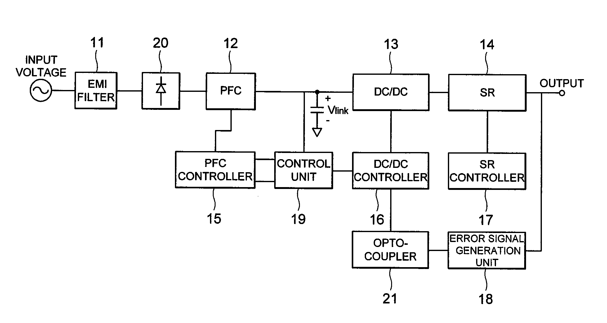
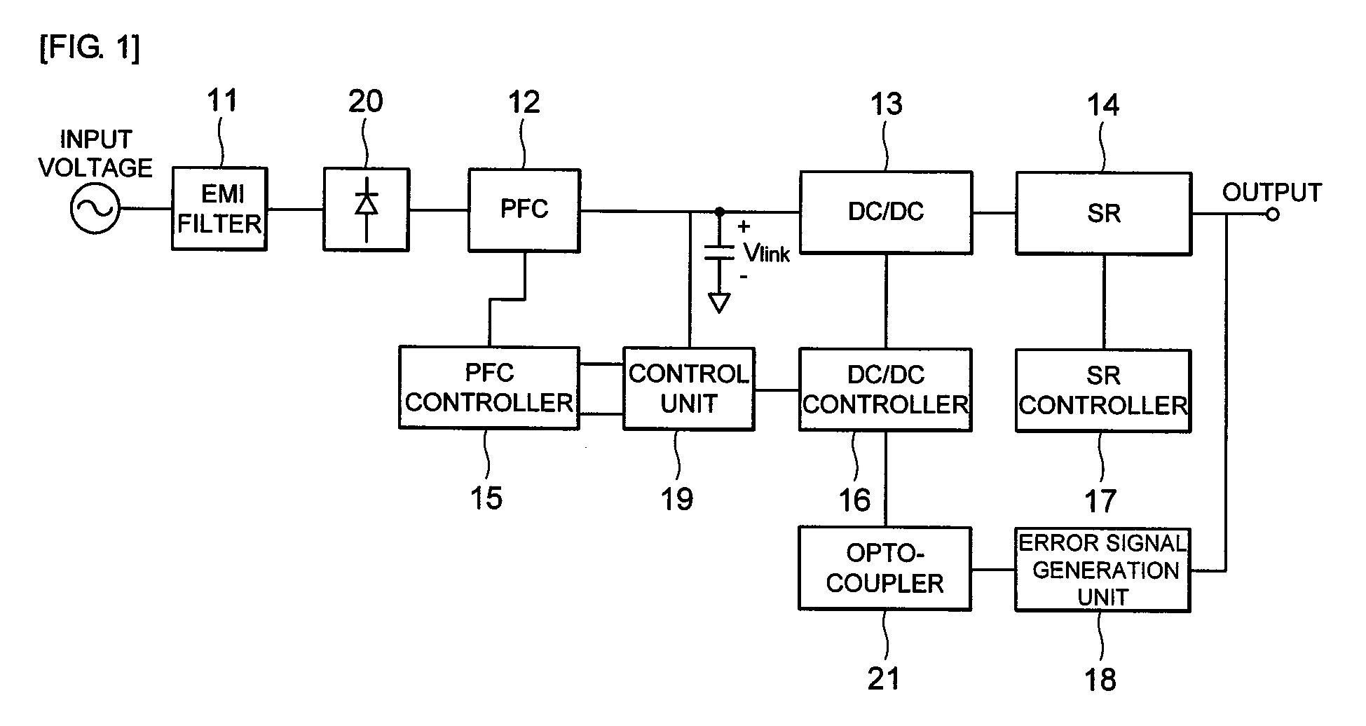
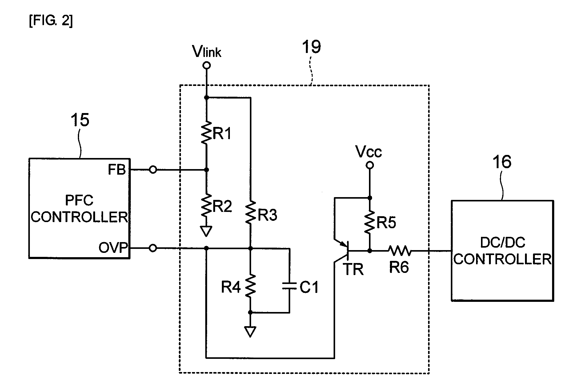
[0027]FIG. 1 is a block diagram showing a switching mode power supply for reducing standby power in accordance with a first embodiment of the present invention, FIG. 2 is a circuit diagram illustrating a control unit of the switching mode power supply for reducing the standby power in accordance with the first embodiment of the present invention and FIG. 3 is a graph illustrating operation waveforms of the switching mode power supply for reducing the standby power in accordance with the first embodiment of the present invention.

[0028]Referring to FIGS. 1 to 3, the switching mode power supply for reducing the standby power in accordance with the first embodiment of the present invention includes an EMI(Electro-Magnetic Interference) filter unit 11, a PFC(Power Factor Correction) unit 12, a DC / DC unit 13, a synchronous rectifier unit 14, a PFC controller 15, a DC / DC controller 16, a synchronous rectifier controller 17, an error signal generation unit 18, and a control unit 19.

[00...

second embodiment

[0043

[0044]FIG. 4 is a block diagram showing a switching mode power supply for reducing standby power in accordance with a second embodiment of the present invention, FIG. 5 is a circuit diagram illustrating a control unit of the switching mode power supply for reducing the standby power in accordance with the second embodiment of the present invention and FIG. 6 is a graph illustrating operation waveforms of the switching mode power supply for reducing the standby power in accordance with the second embodiment of the present invention.

[0045]Referring to FIGS. 4 to 6, the switching mode power supply for reducing the standby power in accordance with the second embodiment of the present invention includes an EMI(Electro-Magnetic Interference) filter unit 41, a PFC(Power Factor Correction) unit 42, a DC / DC unit 43, a synchronous rectifier unit 44, a PFC controller 45, a DC / DC controller 46, a synchronous rectifier controller 47, an error signal generation unit 48, and a control unit 49...


PUM


Abstract

A switching mode power supply includes an EMI filter unit, a PFC unit, a DC / DC unit, a PFC controller including a feedback stage to which a link voltage at an output side of the PFC unit is fed back and an overvoltage protection stage, a DC / DC controller generating a burst mode operation signal in a light-load or no-load condition, an error signal generation unit for sensing an output voltage of the power supply to generate an error signal, and a control unit for enabling the PFC unit to operate in a burst mode by connecting the overvoltage protection stage and the feedback stage. When the error signal is smaller than a predetermined value, the DC / DC controller generates the burst mode operation signal. When the link voltage fed back to the feedback stage exceeds a threshold voltage of the overvoltage protection stage, the PFC controller deactivates the PFC unit.

Description

CROSS-REFERENCE TO RELATED APPLICATIONS[0001]This application claims the benefit of Korean Patent Application No. 10-2008-0130094 filed with the Korea Intellectual Property Office on Dec. 19, 2008, the disclosure of which is incorporated herein by reference.BACKGROUND OF THE INVENTION[0002]1. Field of the Invention[0003]The present invention relates to a switching mode power supply; and, more particularly, to a switching mode power supply for reducing standby power to operate a PFC unit as well as a DC / DC unit in a burst mode in no-load or a light load.[0004]2. Description of the Related Art[0005]It is general that a high power density switching mode power supply is a two stage converter consisting of a PFC(Power Factor Correction) unit for taking full charge of improvement of power factor and harmonic regulation and a DC / DC unit for obtaining a desired output voltage.[0006]In such a two stage converter, although a boost converter is often employed as the PFC unit, a buck converter ...

Claims


Application Information

Patent Timeline
Patent Type & Authority Patents(United States)
IPC IPC(8): H02M3/335
CPCH02M1/4208H02M3/156Y02B70/126Y02B70/10Y02P80/10H02M1/32H02M3/28
Inventor RYU, BYOUNG WOOMOON, GUN WOOCHOI, SEONG WOOKLEE, BYOUNG HEEOH, DONG SEONG
Owner SOLUM CO LTD
Learn More