Virtual dial-up protocol for network communication
What is Al technical title?
Al technical title is built by PatSnap Al team. It summarizes the technical point description of the patent document.
a virtual dial-up and network communication technology, applied in the field of virtual dial-up systems, can solve the problem that the up server will not receive any password information, and achieve the effect of large investments in access and core infrastructur
Inactive Publication Date: 2012-06-05
CISCO TECH INC
View PDF49 Cites 7 Cited by
Summary
Abstract
Description
Claims
Application Information
AI Technical Summary
This helps you quickly interpret patents by identifying the three key elements:
Problems solved by technology
Method used
Benefits of technology
[0015]L2F provides the ability to multiplex multiple clients within a tunnel and allows the home gateway to tell different tunnels apart. From a L2F header, the home gateway determines what NAS and client the data is coming from and accordingly connects the client to the correct virtual interface. The tunneling technique used in conjunction with L2F does not require authentication or address assignment from the ISP. Thus, termination protocols and updating requirements normally performed by the ISP, and which are incompatible with private networks such as IPX and Appletalk, are not necessary.
[0016]L2F allows multiple protocols and unregistered IP addresses to be used across existing internet infrastructure. Thus, very large investments in access and core infrastructure can be shared.
Problems solved by technology
Thus, if the remote client dials up to the wrong location and the client responds, the dial-up server will not receive any password information that can be used for unauthorized access to the local network.
Method used
Image
Click on the blue label to locate the original text in one second.
Reading with bidirectional positioning of images and text.
Examples
Embodiment Construction
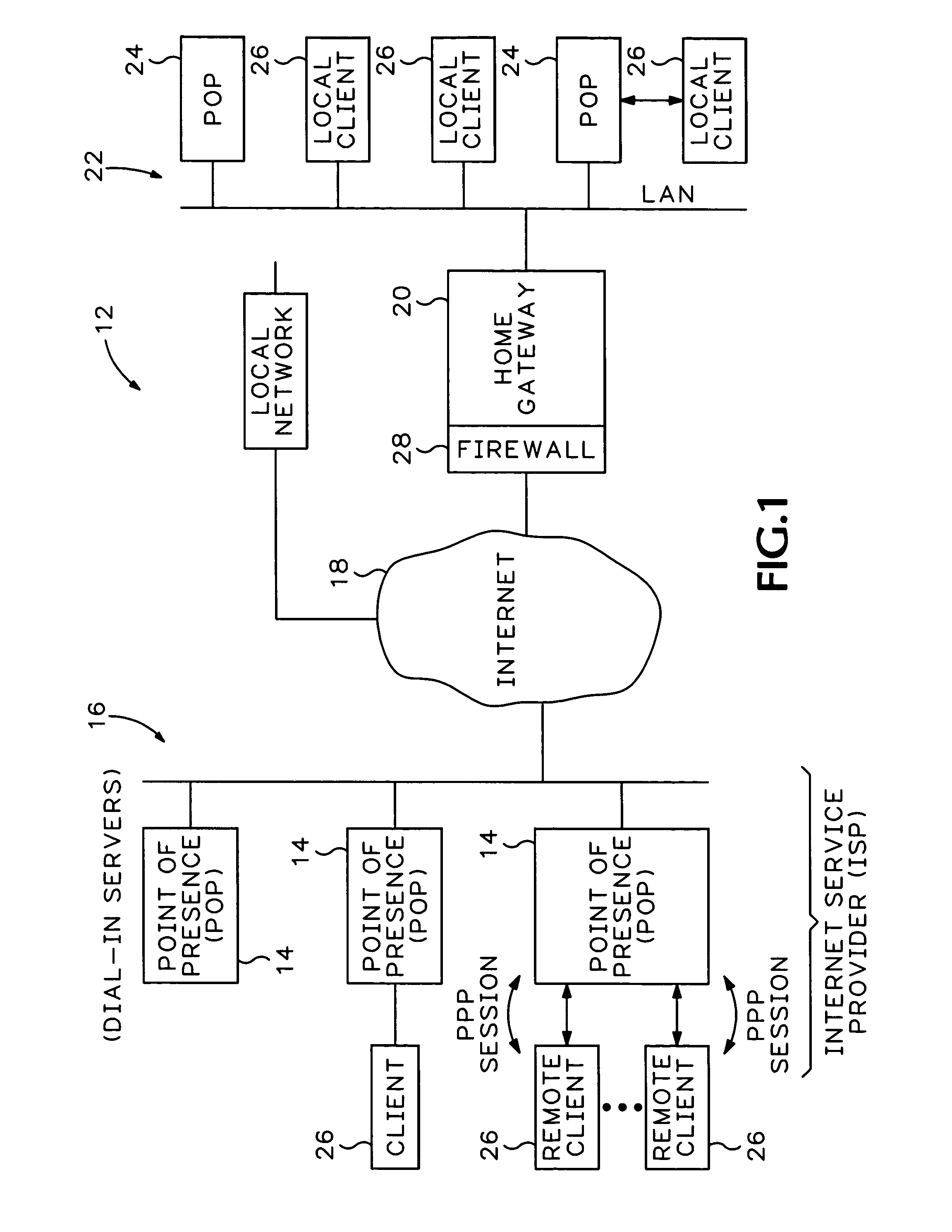
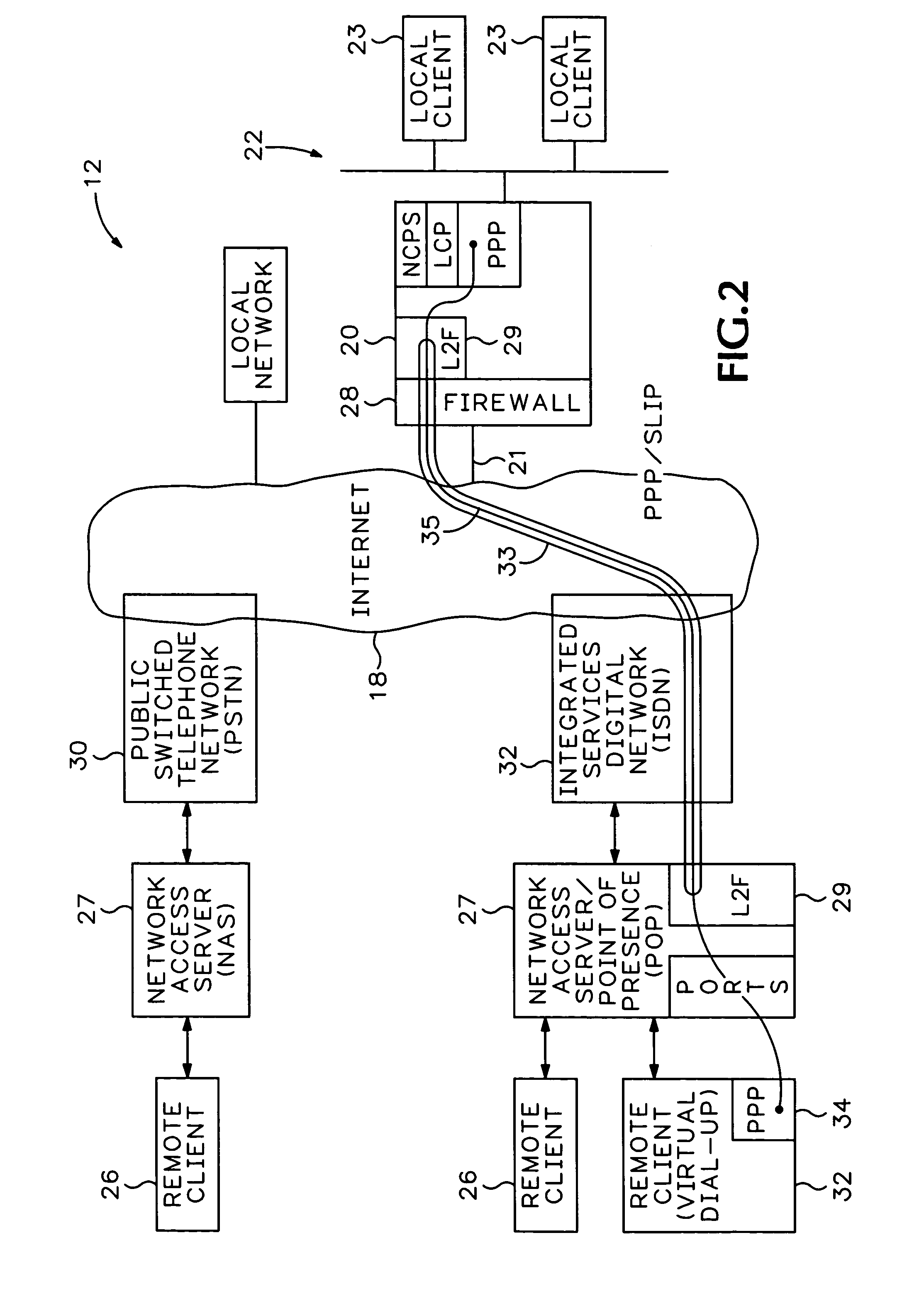
[0027]Referring to FIG. 2, remote client 26 is coupled to an Internet Service Provider (ISP) network access server (NAS) 27 that accesses the internet infrastructure 18 via a Public Switched Telephone Network (PSTN) 30 (i.e., async PPP via modems). Remote client 32 is coupled to a NAS 27 through a port and accesses the internet 18 via an Integrated Services Digital Network (ISDN) 32 (i.e., synchronous PPP access). A private Local Area Network (LAN) 22 includes local clients 23 and is connected to internet 18 through a home gateway 20 which includes a firewall 28. NAS 27 is alternatively defined as an ISP Point of Presence (POP).
[0028]The hardware and software required to generally operate NAS 27, PSTN 30, ISDN 32, internet infrastructure 18, home gateway 20, firewall 28 and local clients 26 and remote clients 26 and 32 are all well known to those skilled in the art and are, therefore, not described in detail.
[0029]Remote client 32 accesses LAN 22 through a virtual dial-up session ac...
PUM
Abstract
A layer two forwarding protocol (L2F) provides virtual direct dial-up service into private networks through public internet service providers. An authorized remote client appears as a direct dial-up client to the home gateway, even through the client is accessing the home gateway remotely through the ISP. The new forwarding protocol allows the remote client to conduct point-to-point link protocols, such as point-to-point protocol (PPP) and serial line interface protocol (SLIP) directly with the local network home gateway. The network access server changes from a routing mode where a communication protocol is conducted with the client to a switching mode where the POP simply sends data from one port to a tunnel. The tunnel then transmits the data to another port, regardless of the header information on transmitted data packets. The remote client can then be managed through databases controlled by the local network and gain access to resources not typically accessible through the internet. The layer two forwarding protocol conducts an independent authorization session to prevent unauthorized access to the private network and provides point-to-point protocol transport over the internet independently of internet transport protocols.
Description
[0001]This application is a continuation of U.S. Ser. No. 10 / 264,037 filed Oct. 2, 2002, now U.S. Pat. No. 6,754,712, issued Jun. 22, 2004, which is a continuation of U.S. patent application Ser. No. 09 / 903,796, filed Jul. 11, 2001, now U.S. Pat. No. 6,487,598, issued Nov. 26, 2002, which claims the benefit of is a continuation of U.S. patent application Ser. No. 09 / 309,166, filed May 10, 1999, now U.S. Pat. No. 6,308,213, issued Oct. 23, 2001, which claims the benefit of is a continuation of U.S. patent application Ser. No. 08 / 687,973 filed Jul. 29, 1996, now U.S. Pat. No. 5,918,019, issued Jun. 29, 1999.BACKGROUND OF THE INVENTION[0002]This invention relates generally to network systems and more particularly to a virtual dial-up system used for accessing a private local network through an internet access service.[0003]FIG. 1 is a prior art internetwork system 12 which includes multiple dial-up network access servers (NAS) 14 also referred to as points of presence (POPs). The POPs ...
Claims
Application Information
Patent Timeline
Application Date:The date an application was filed.
Publication Date:The date a patent or application was officially published.
First Publication Date:The earliest publication date of a patent with the same application number.
Issue Date:Publication date of the patent grant document.
PCT Entry Date:The Entry date of PCT National Phase.
Estimated Expiry Date:The statutory expiry date of a patent right according to the Patent Law, and it is the longest term of protection that the patent right can achieve without the termination of the patent right due to other reasons(Term extension factor has been taken into account ).
Invalid Date:Actual expiry date is based on effective date or publication date of legal transaction data of invalid patent.