Floor panel and method for the manufacture thereof

a technology of floor panels and insulating layers, applied in the field of floor panels, can solve the problems of affecting the sound quality of the floor panel, and the sound of clacking, etc., and achieves the effect of small sound absorption effect of the insulating layer provided under the floor panel

Active Publication Date: 2012-06-12
FLOORING IND LTD
View PDF26 Cites 141 Cited by
  • Summary
  • Abstract
  • Description
  • Claims
  • Application Information

AI Technical Summary

Benefits of technology

[0013]By integrating one or more sound-absorbing layers into the floor panel, more particularly at a distance above the underside, as well as at a distance below the top surface, it is obtained that, on one hand, such sound-absorbing layer, independent from the thickness of the floor panel, can be positioned relatively close to the upper surface, whereas, on the other hand, the global structure of such floor panel still can be kept relatively thick and stable. Tests have shown that by integrating the sound-absorbing layer, better results are obtained, on one hand, as the thickness of the material situated thereabove, in which the sound substantially propagates, is reduced and, on the other hand, in that a multilayer construction is created, which obviously also contributes to the desired effect in an advantageous manner.
[0055]As, according to this method, use is made of a windable sound-absorbing material, this latter is easy to handle in a production process, as then, the sound-absorbing material easily can be unwound and subsequently be attached upon the plate-shaped structural basic layers. Also, it possibly may be directly fixed upon such basic layer by rolling it thereon, by the intermediary of an adhesive agent, adhesive layer or the like.

Problems solved by technology

The floor panels of this type known up to now have the disadvantage that, when walked upon, they are causing a kind of “clacking” sound.
In particular the higher tones forming the basis of this sound are experienced as annoying.
However, the sound-absorbing effect of an insulating layer provided under the floor panels seems to be rather small, in particular if one intends to reduce reflection sounds, more particularly the so-called “footfall sound”.
The disadvantage of such floor panels, however, consists in that the appearance of the decorative surface remains limited to the appearance of cork or printed cork, as a consequence of which the usage possibilities are strongly limited.

Method used


Image

  • Floor panel and method for the manufacture thereof
  • Floor panel and method for the manufacture thereof
  • Floor panel and method for the manufacture thereof

Examples


Embodiment Construction

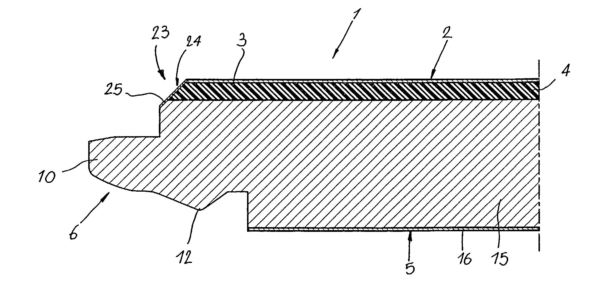
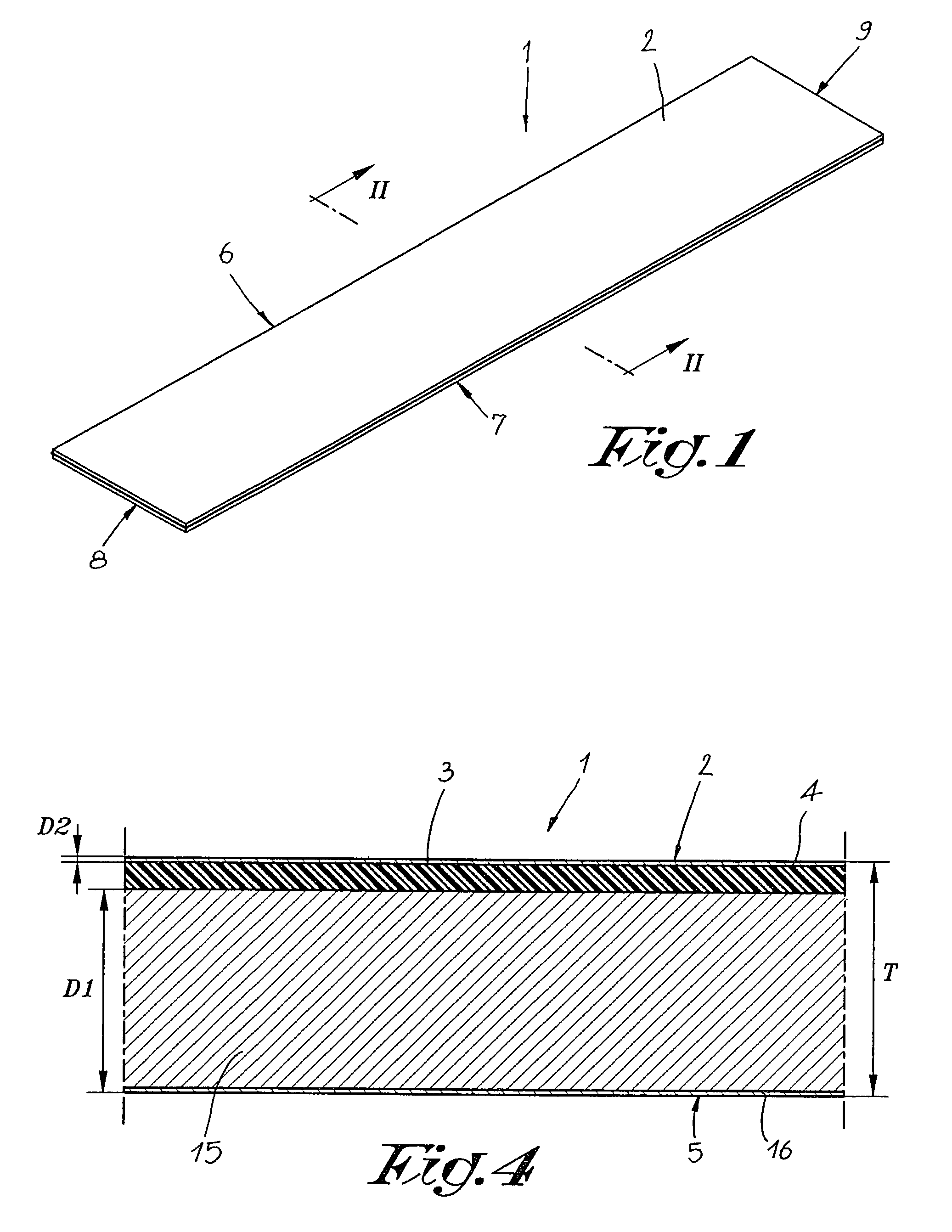
[0066]As represented in FIGS. 1 and 2, the invention relates to a floor panel 1 which is provided with a hard or relatively hard top layer 3 at the upper side 2.

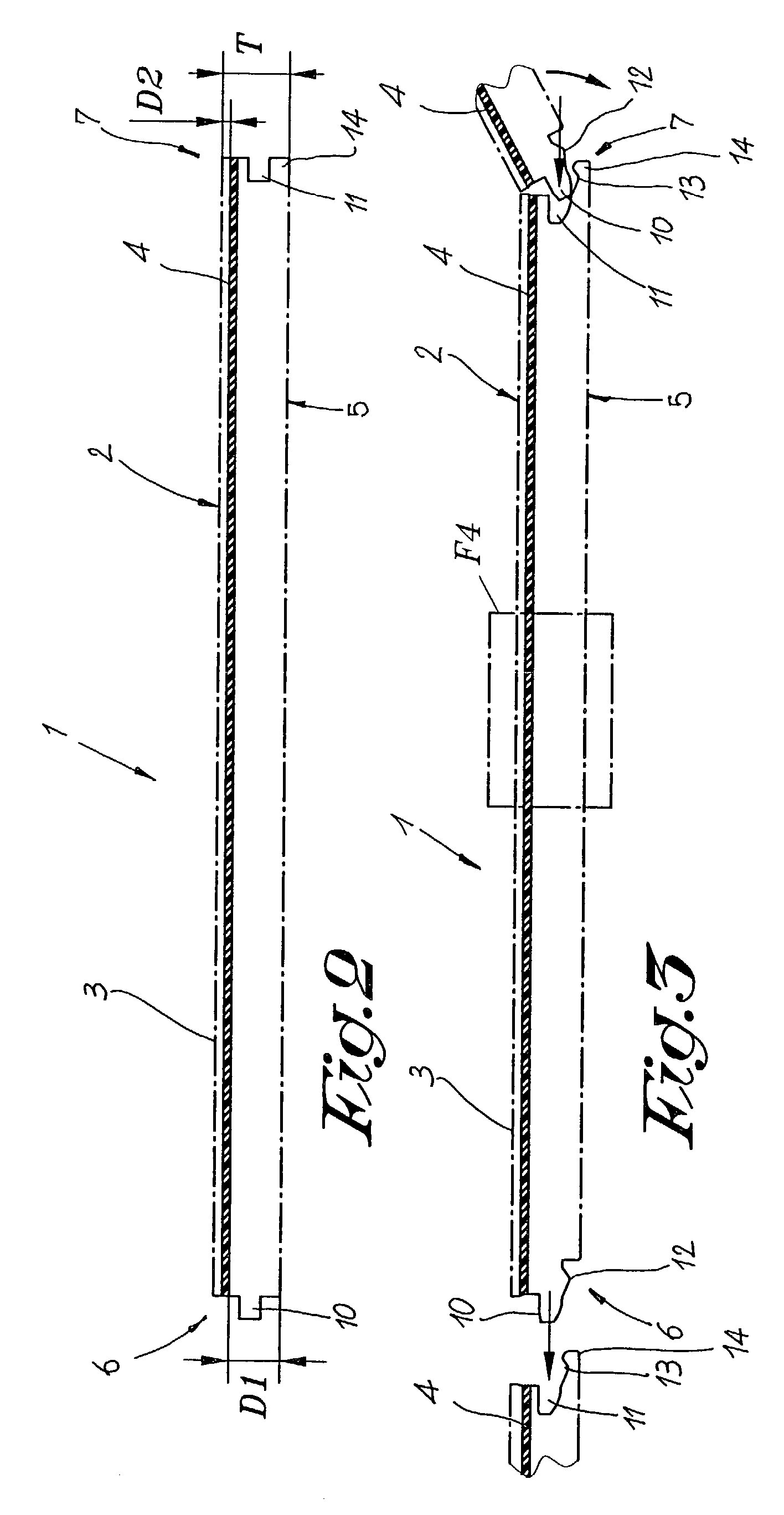
[0067]As schematically represented in FIG. 2, this floor panel 1 according to the invention comprises at least one sound-absorbing layer 4 which is integrated into the floor panel 1 itself, in other words, is incorporated into the structure of the floor panel 1.

[0068]Viewed according to the thickness T of the floor panel 1, as represented, the sound-absorbing layer 4 thus is situated at a distance D1 above the underside 5 of the floor panel 1, as well as at a distance D2 below the upper side 2.

[0069]As explained in the introduction, the distance D2 preferably is as small as possible, and in a practical application, this distance thus will be smaller than 4 mm, or even better, will be smaller than or equal to 2 mm.

[0070]As represented in FIG. 2, the floor panel 1, in a known manner, can be provided with coupling parts 10-11 a...


PUM

PropertyMeasurementUnit
distanceaaaaaaaaaa
thicknessaaaaaaaaaa
thicknessaaaaaaaaaa

Abstract

Floor panel of the type comprising a hard top layer (3) forming a decorative surface, from which, together with other identical or similar floor panels (1), a floor covering can be formed, wherein this floor panel (1) includes at least one sound-absorbing layer (4) which is integrated into the floor panel (1) and is located between other layers of this floor panel (1).

Description

BACKGROUND OF THE INVENTION[0001]A. Field of the Invention[0002]This invention relates to a floor panel and a method for the manufacture thereof.[0003]B. Discussion of Related Art[0004]More particularly, the invention relates to a floor panel of the type comprising a hard top layer forming a decorative surface, from which, together with other identical or similar floor panels (1), a floor covering can be formed.[0005]In particular, the invention relates to so-called laminated floor panels, such as, for example, described in the international patent application No. WO 97 / 47934.[0006]By a floor panel with a hard top layer, any form of panel has to be understood which has a hard or relatively hard surface at the side which is to be walked upon, which feature does not exclude that softer materials are incorporated in the panel, nor excludes that the panel can show a certain flexibility.[0007]The floor panels of this type known up to now have the disadvantage that, when walked upon, they...

Claims


Application Information

Patent Timeline
Patent Type & Authority Patents(United States)
IPC IPC(8): E04F15/22B32B7/022B32B21/02E04F15/02E04F15/04E04F15/20
CPCB32B7/02B32B21/02E04F15/02E04F15/02033E04F15/181E04F15/20Y10T29/49826E04F2201/0107E04F2201/0115E04F2201/0153E04F2201/0161E04F2290/042B32B7/022B32B9/042B32B2317/02B32B2419/04B32B2307/10
Inventor THIERS, BERNARDHOCHEPIED, PETER
Owner FLOORING IND LTD
Why Eureka
Try Eureka