Deployable automated vent cover device

a technology of automatic vent cover and vent cover, which is applied in the direction of water supply installation, lighting and heating apparatus, heating types, etc., can solve the problems of applicability shutdown, and achieve the effect of reducing the prevalence and threat of nonsocial infections

Active Publication Date: 2012-06-12
ALTAPURE
View PDF20 Cites 21 Cited by
  • Summary
  • Abstract
  • Description
  • Claims
  • Application Information

AI Technical Summary

Benefits of technology

[0066]The following embodiments are intended to augment current methods utilized in the surgical suite to further reduce the continued prevalence and threat of nonsocial infections. Despite the use of directed air flow, ultra violet light and sterile site preparation, MRSA and other serious infection causing pathogens continue to directly cause the deaths of over 102,000 individuals per year.
[0067]An apparatus and method of an embodiment of the present invention, briefly summarized, comprises administering an aerosol and / or vapor into one or more enclosed area(s) where the enclosed area(s) can have, without limitation, one or more opening(s) or orifice(s), and one or more object(s) can be positioned or inserted through these opening(s) or orifice(s), and the direct or indirect contact or interface of the object(s) with these opening(s) or orifice(s) results or causes the enclosed area(s) to become, without limitation, effectively sealed. The object(s) can, without limitation, be positioned or inserted completely through the enclosed area in any orientation, through the one or more opening(s) or orifice(s). The direct or indirect interface(s) between the object(s) or surface(s) and the one or more wall(s) of the enclosed area can be, without limitation, sealed or semi sealed. This further clarifies the initial submission for the present invention. The enclosed area can also incorporate various means for the introduction or supply of one or more sources of pressurized air or gas, or any vacuum, into any location of the enclosed area, as well as across or over any of these one or more door(s) or opening(s) to the enclosed area(s). This enclosed system combined with a pressurized air flow and vacuum near the door(s) opening(s), allows work, such as but not limited to, surgical procedures, to be performed in an environment where all of the targeted surfaces are treated, and the air traveling over, under, or across the door(s) allows that sterile environment to be effectively maintained.

Problems solved by technology

The transducers are submerged in one or more tanks or reservoirs, and cause a surface disturbance, which results in the formation of an aerosol of the liquid in the tanks or reservoir(s).
The tanks or reservoirs also have a means to sense if they are under or overfilled, and can cause the apparatus to shut down if this occurs.

Method used


Image

  • Deployable automated vent cover device
  • Deployable automated vent cover device
  • Deployable automated vent cover device

Examples


Embodiment Construction

[0144]Detailed references to the embodiments of the invention, are illustrated in the accompanying drawings that serve as examples. While the invention will be described in conjunction with the embodiments, it is understood that they are not intended to limit the invention to those embodiments. On the contrary, the invention is intended to cover alternatives, modifications, and equivalents, which may be included within the spirit and scope of the invention as defined by the appended claims.

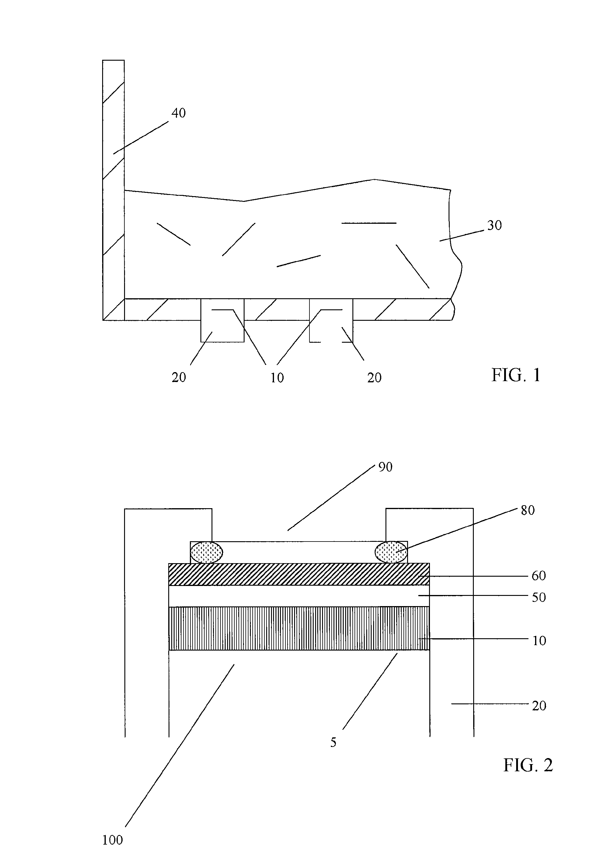
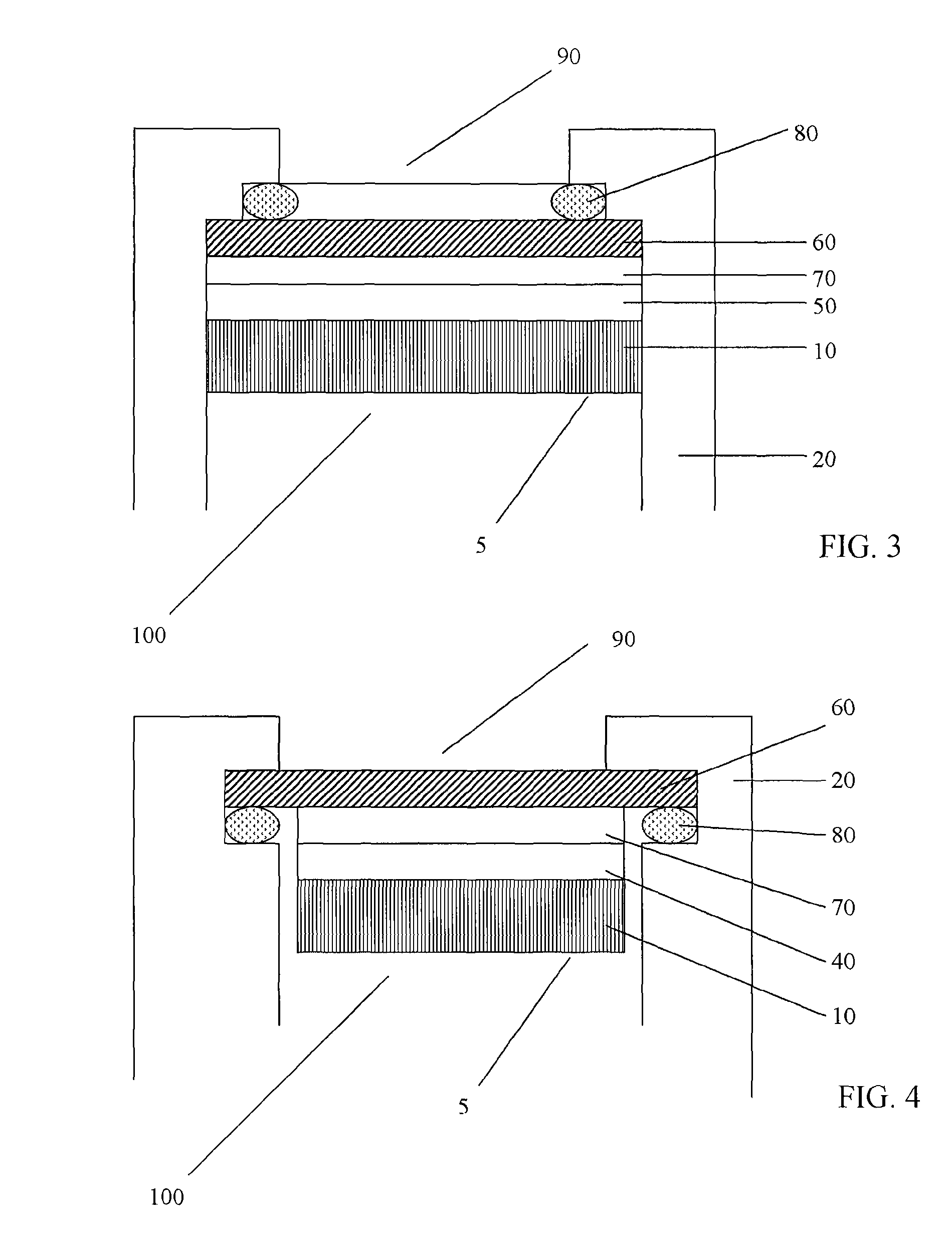
[0145]As illustrated in FIGS. 1-5B, an embodiment of the invention includes a method and apparatus for protecting and enhancing the performance of one or more aerosol generating ultrasonic transducer(s) (10) by adhering one or more protective barrier(s) (60) to a transducer(s) (10). Unless otherwise stated, adhering in this specification includes, but is not limited to adhering, coupling, gluing, attaching, cementing, cohering, fastening, pasting, depositing, applying, melting onto or melting toge...


PUM


Abstract

A deployable automated vent cover device includes a vent cover and a telescopic pole. The vent cover includes a vent base, a first vent door, a second vent door and a release mechanism. The release mechanism includes a solenoid, a pivot release, a first latch device and a second latch device. The vent base preferably includes a base plate with two openings, and a vent seal. The first and second vent doors are pivotal attached to the base plate. The first latch device is retained on the base plate and the second latch device is retained on the base plate. The first and second latch devices retain the first and second vent doors in a closed orientation. The pivot release is pivotally connected to the solenoid and to the first and second latch devices. The solenoid is actuated to open the first and second vent doors through the pivot release.

Description

CROSS-REFERENCES TO RELATED APPLICATIONS[0001]This is a non-provisional patent application, which takes priority from provisional patent application No. 61 / 295,869, filed on Jan. 18, 2010.TECHNICAL FIELD OF THE INVENTION[0002]The present invention relates to improved apparatuses and methods for the generation and application of an ultrasonically generated aerosol for uses including but not limited to the sanitization, detoxification, disinfection, high-level disinfection, or sterilization of one or more areas and the surfaces in those areas, as well as the delivery of other types of liquid agents, for variousBACKGROUND OF THE INVENTION[0003]The apparatus described in U.S. Pat. No. 4,366,125, which is incorporated herein by reference in its entirety, including any references cited therein, generates a hydrogen peroxide mist by an ultrasonic wave vibrator. The mist adheres to the surface of materials being sterilized and is then irradiated with ultraviolet-ray lamps. U.S. Pat. Nos. 5,...

Claims


Application Information

Patent Timeline
Patent Type & Authority Patents(United States)
IPC IPC(8): F16K31/56F24F13/15F16K31/46F16K35/14
CPCA61L9/14A61L2209/132Y10T137/87483
Inventor RICCIARDI, JONATHAN J.RICCIARDI, CARL L.WOLF, II, JOHN D.
Owner ALTAPURE
Why Eureka
Try Eureka