Cathode discharge apparatus

a discharge apparatus and cathode technology, applied in the direction of electrical devices, gas discharge lamp details, electric discharge tubes, etc., can solve the problems of difficult to raise the conversion efficiency of solar cells, limited utilization rate of solar energy, and urgent problem of looking for substitute energies, etc., to achieve high ionization and high uniformity

Active Publication Date: 2012-06-12
IND TECH RES INST
View PDF9 Cites 0 Cited by
  • Summary
  • Abstract
  • Description
  • Claims
  • Application Information

AI Technical Summary

Benefits of technology

[0005]The present invention provides the cathode discharge apparatus able to generate the plasma with high uniformity and high ionization.

Problems solved by technology

Under the condition of the predictable shortage of the fossil fuel in the near future, looking for the substituted energies becomes an urgent issue.
However, the utilization rate of the solar energy is limited due to the conversion efficiency of the solar cell.
Nevertheless, it is not easy to raise the conversion efficiency of the solar cell owing to the solid state properties of the semiconductor, but it is feasible to enlarge the exposure area of the solar cell.
Currently, the plasma apparatuses have the uniformity problem for the large-size plasma processes applied to TFT-LCD, thin film solar cells, etc.

Method used


Image

  • Cathode discharge apparatus
  • Cathode discharge apparatus
  • Cathode discharge apparatus

Examples


first embodiment

[0035

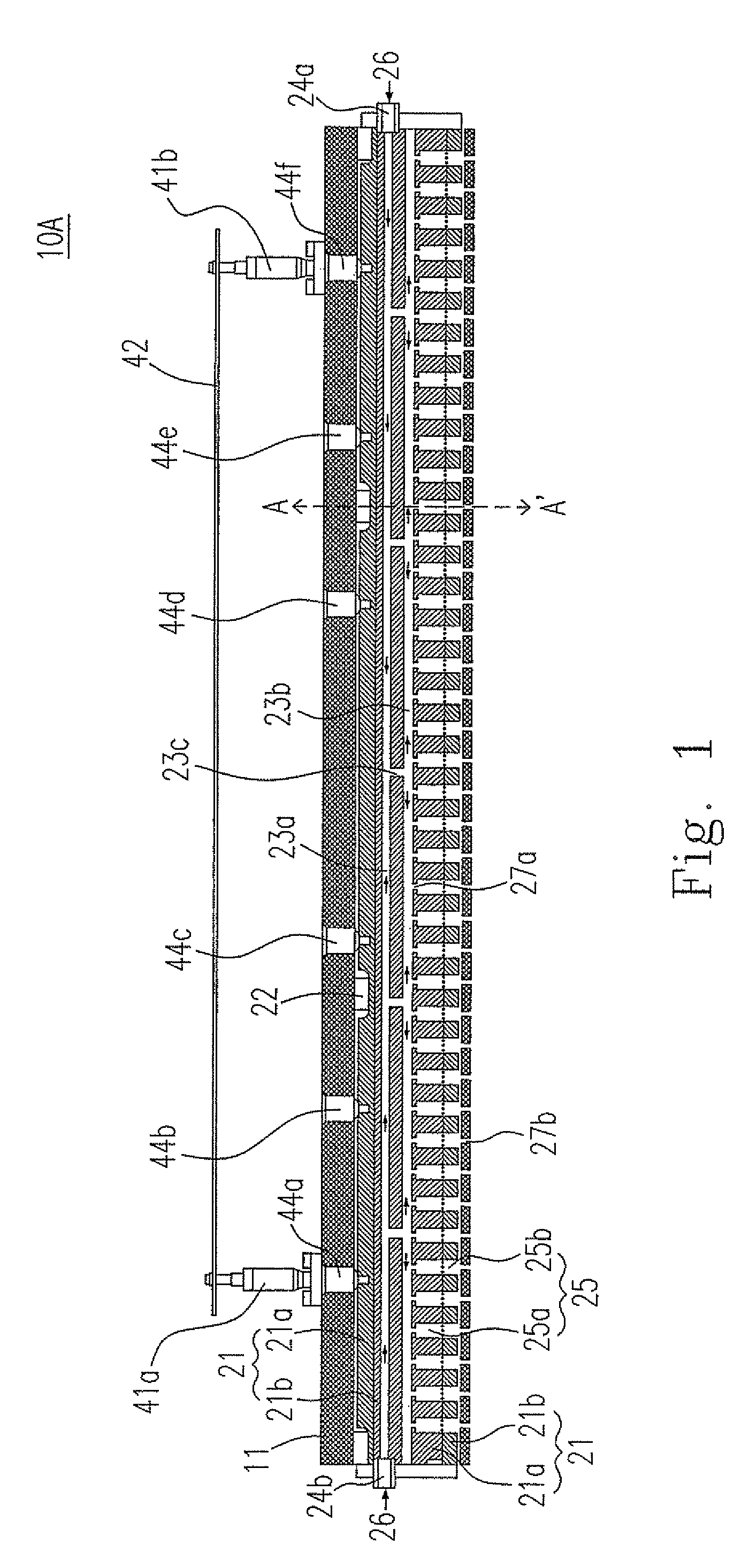
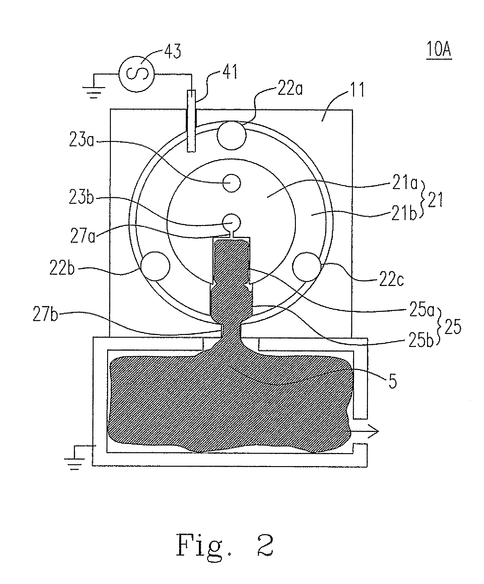
[0036]FIG. 1 is the schematic diagram showing the cross section of the cathode discharge apparatus from the side view according to the first embodiment of the present invention. FIG. 2 is the schematic diagram showing the cross section of the cathode discharge apparatus in FIG. 1 along the A-A line according to the first embodiment of the present invention. Please refer to FIG. 2. The cathode discharge apparatus 10A includes the anode 11, the cathode 21 and the cathode chamber 25. The cathode 21 is located inside the anode 11. The insulators 22a, 22b and 22c separate the cathode 21 and anode 11.

[0037]The cathode 21 includes plural cathode chambers 25, and can be divided into the first portion 21a and the second portion 21b, which may be two pieces contacted with each other for facilitating the machining process, or may be made in one piece. Each of the cathode chambers 25 can be divided into the first portion 25a and the second portion 25b, where the first portion 25a of the ca...

second embodiment

[0047

[0048]The cathode discharge apparatus of the present embodiment is almost identical to that in the first embodiment. The only difference between the present embodiment and the first embodiment is: in the first embodiment, the cathode chambers 25 are designed to be parallel to one another and are oriented vertically downward, so the plasma is injected vertically downward via the chamber outlets 27b; while in the present embodiment, the cathode chambers 25 are designed to tilt at an angle relative to the vertical direction. The FIG. 3 is the schematic diagram showing the cross section of the cathode discharge apparatus according to the second embodiment of the present invention. The difference between the present embodiment and the first embodiment can be told by referring to FIGS. 2 and 3 simultaneously. The cathode chambers of the present embodiment tilts at a small angle, e.g. 5-30 degree, relative to the vertical direction, and can be aligned in a way, where the odd-numbered ...

third embodiment

[0049

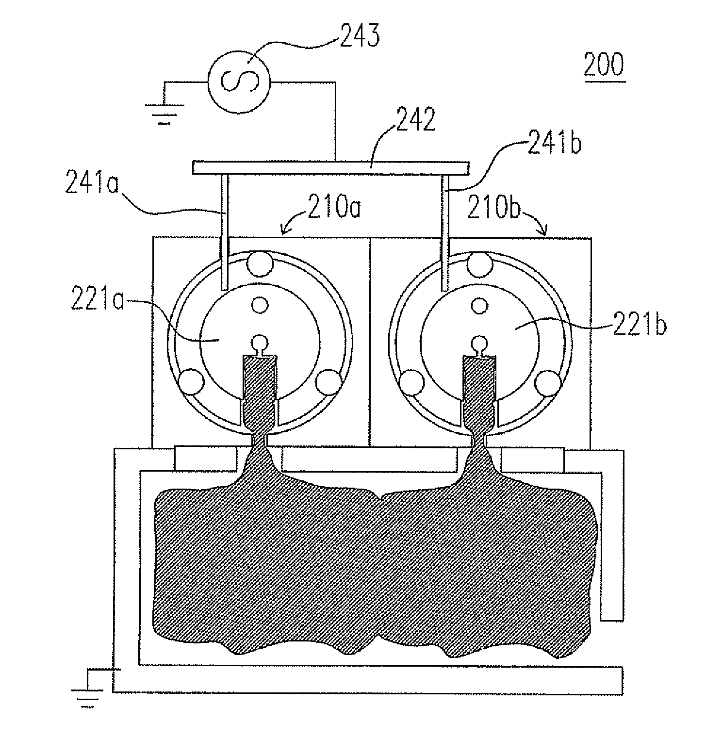
[0050]Please refer to FIG. 4, which is the schematic diagram showing the cross section of the cathode discharge apparatus according to the third embodiment of the present invention. In this embodiment, the cathode discharge apparatus 100 includes an anode 110 and two cathodes 121a and 121b, where the structure of each cathode is almost the same as that of the first embodiment. That is to say, two parallel aligned tubular cathodes 121a and 121b are enclosed inside the anode 110, and share the single anode 110. The two cathodes 121a and 121b have the electrical feedthroughs 141a and 141b, respectively. The cathode discharge apparatus 100 can contain the electrode connecting element 142 and the power supply 143, both of which are electrically connected, and the power supply 143 can provide power to the cathodes 121a and 121b through the electrode connecting element 142 and the electrical feedthroughs 141a and 141b.

[0051]FIG. 5 is the schematic diagram showing the 3-dimensinal vie...


PUM


Abstract

A cathode discharge device is provided. The cathode discharge apparatus includes an anode, a cathode and plural cathode chambers. The cathode is located inside the anode, where the cathode has plural flow channels and at least one flow channel hole, and the plural flow channels are connected to one another through the flow channel hole. The plural cathode chambers are located inside the cathode, wherein each of the cathode chambers has a chamber outlet and a chamber inlet connected with at least one of the flow channels.

Description

FIELD OF THE INVENTION[0001]The present invention relates to a cathode discharge apparatus, especially to a hollow cathode discharge apparatus for the large area coating.BACKGROUND OF THE INVENTION[0002]Under the condition of the predictable shortage of the fossil fuel in the near future, looking for the substituted energies becomes an urgent issue. Among various substituted energies, the solar energy is the one with the best economy and environment protection. Therefore, several countries, such as USA and Germany, have included the solar energy as the national energy development project. However, the utilization rate of the solar energy is limited due to the conversion efficiency of the solar cell. There are two ways to raise the utilization rate. One is to raise the conversion efficiency of the solar cell, and the other is to reduce the production cost of the solar cell. Nevertheless, it is not easy to raise the conversion efficiency of the solar cell owing to the solid state prop...

Claims


Application Information

Patent Timeline
Patent Type & Authority Patents(United States)
IPC IPC(8): H01J17/26
CPCH01J37/3244H01J37/32449
Inventor TUNG, FU-CHINGSHEN, TEAN-MUHO, JUNG-CHENWU, PEI-SHANCHEN, CHIA-MINGCHEN, KUAN-CHOUCHIEN, JUNG-CHENLIANG, MUH-WANG
Owner IND TECH RES INST
Why Eureka
Try Eureka