Method and apparatus for configuring a wireless sensor

a wireless sensor and wireless technology, applied in the direction of electric controllers, ignition automatic control, instruments, etc., can solve the problem of increasing the likelihood that the load control device may not detect the presence of a user

Active Publication Date: 2012-06-12
LUTRON TECH CO LLC
View PDF196 Cites 480 Cited by
  • Summary
  • Abstract
  • Description
  • Claims
  • Application Information

AI Technical Summary

Benefits of technology

[0010]A process of affixing an electronic device to a ceiling panel is also described herein. The process comprises the steps of: (1) inserting parallel, spaced legs of a single wire through openings in a flat adapter plate until a base portion of the wire is pressed flat against one surface of the adapter plate; (2) forcing the spaced legs of the wire through respective spaced points on a first surface of the ceiling panel; (3) manually bending the legs against a second surface opposite the first surface of the ceiling panel to press and hold the adapter plate against the first surface of the ceiling panel; and (4) removably connecting the electronic device to the adapter plate.

Problems solved by technology

However, since the wall-mounted load control device is mounted to a wall in a standard electrical wallbox (i.e., as a replacement for a standard light switch), the detection of energy by the PIR detector may be hindered due to the direction that the load control device is facing and by obstacles in the space, thus increasing the likelihood that the load control device may not detect the presence of a user.

Method used


Image

  • Method and apparatus for configuring a wireless sensor
  • Method and apparatus for configuring a wireless sensor
  • Method and apparatus for configuring a wireless sensor

Examples


first embodiment

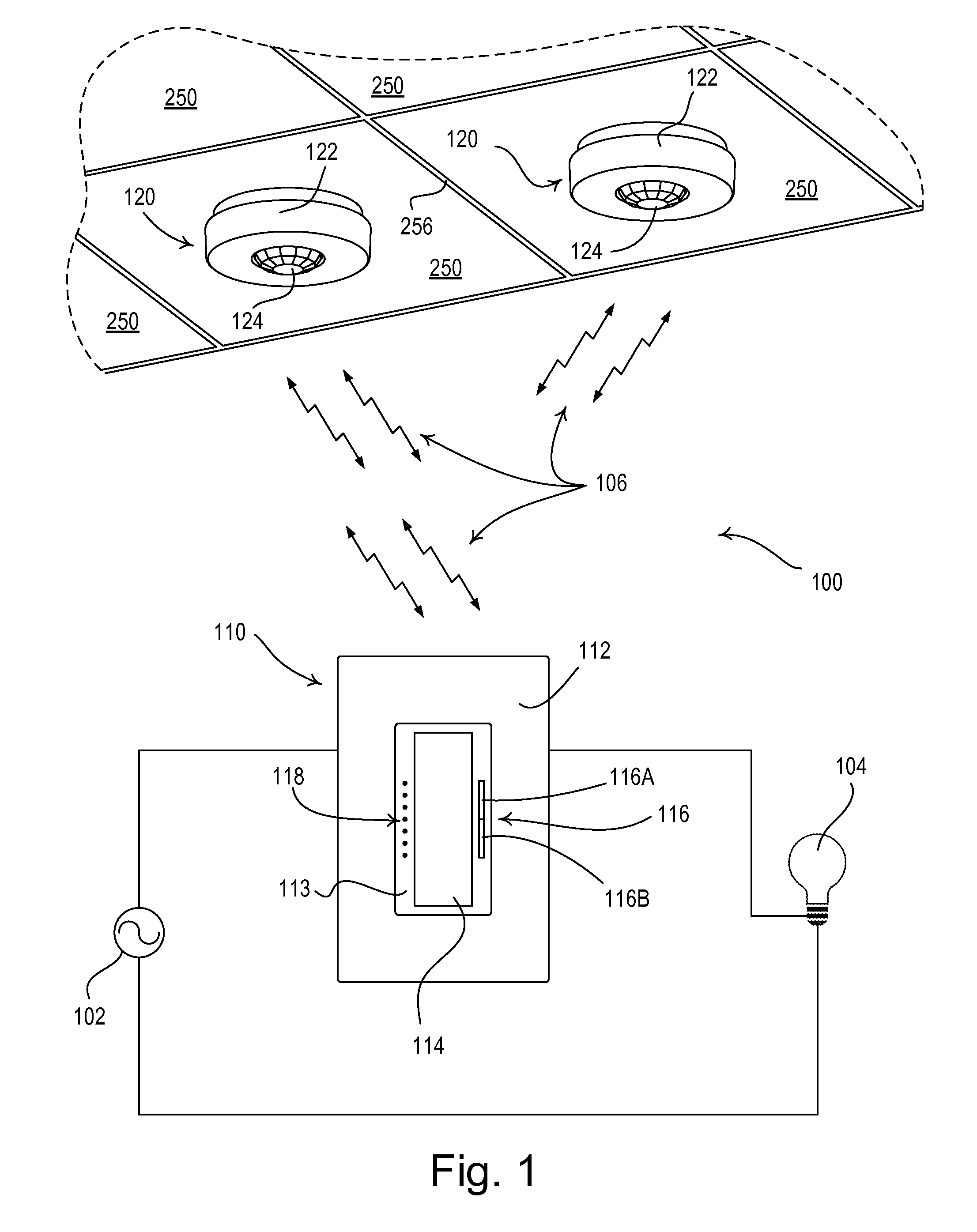
[0034]FIG. 1 is a simple diagram of a radio-frequency (RF) lighting control system 100 comprising a dimmer switch 110 and two remote occupancy sensors 120 (e.g., passive infrared sensors) according to the present invention. The dimmer switch 110 is adapted to be coupled in series electrical connection between an AC power source 102 and a lighting load 104 for controlling the amount of power delivered to the lighting load. The dimmer switch 110 may be adapted to be wall-mounted in a standard electrical wallbox, and comprises a faceplate 112 and a bezel 113 received in an opening of the faceplate. The dimmer switch 110 further comprises a control actuator 114, i.e., a button, and an intensity adjustment actuator 116. Actuations of the control actuator 114 toggle, i.e., turn off and on, the lighting load 104. Actuations of an upper portion 116A or a lower portion 116B of the intensity adjustment actuator 116 respectively increase or decrease the amount of power delivered to the lightin...

second embodiment

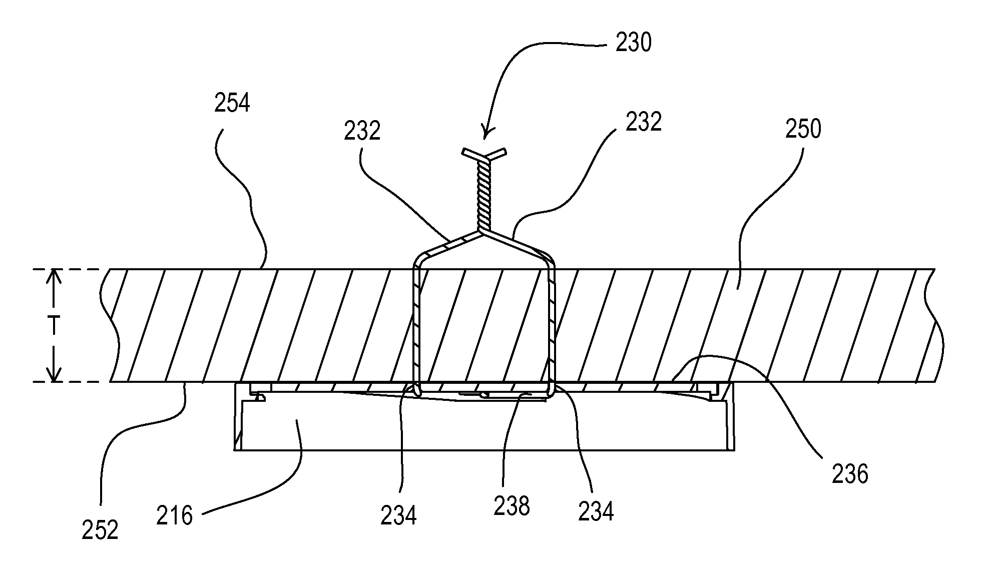
[0063]FIG. 15 is a diagram of an RF lighting control system 800 having an occupancy sensor 820 according to the present invention. The occupancy sensor 820 is releasably attached to the metal grid structure 256 that holds up the drop ceiling panels 250. FIG. 16 is a rear perspective view of the occupancy sensor 820. The occupancy sensor 820 comprises two magnets 850 attached (e.g., glued) to the rear surface 236 of the mounting plate 216, so that the occupancy sensor may be magnetically attached (and thus releasably attached) to the grid structure 256. The magnets 850 may comprise, for example, rare earth Neodymium-Iron-Boron magnets, each having a diameter of approximately 0.25 inch and a height of approximately 0.125 inch. The magnets 850 are arranged along a line that runs through the center of the circle formed by the rear surface 236 of the mounting plate 216, such that approximately one-half of the occupancy sensor 820 is located on each side of the grid structure 256 to which...


PUM

PropertyMeasurementUnit
yield strengthaaaaaaaaaa
elastic modulusaaaaaaaaaa
diameteraaaaaaaaaa

Abstract

A wireless sensor for a load control system is adapted to be releasably mounted to a surface, such as a drop ceiling panel, to allow the optimum location of the sensor to be determined. A releasable mounting means of the sensor comprises two posts extending perpendicularly from a rear surface of the sensor. Each post has a small diameter and is rigid enough to pierce the panel without creating a large aesthetically-displeasing hole. The sensor may be permanently affixed to the panel by bending the posts at a rear surface of the panel without the use of a tool, such that the panel is captured between the mounting plate and the deformed posts. The sensor further comprises multiple test buttons provided on an outwardly-facing surface of the sensor for separately testing the communications of the load control system and the operation of the sensor. Alternatively, the releasable mounting means may comprise one or more magnets for magnetically coupling the sensor to a grid structure of the ceiling.

Description

BACKGROUND OF THE INVENTION[0001]1. Field of the Invention[0002]The present invention relates to occupancy and vacancy sensors for detecting an occupancy or a vacancy condition in a space, and more particularly, to a wireless load control system including a plurality of battery-powered occupancy or vacancy sensors having releasable mounting means for allowing the sensors to be easily fixed in a position and then released from that position during configuration of the load control system, such that the optimum locations of the sensors may be determined.[0003]2. Description of the Related Art[0004]Occupancy and vacancy sensors are often used to detect occupancy and / or vacancy conditions in a space in order to control an electrical load, such as, for example, a lighting load. An occupancy sensor typically operates to turn on the lighting load when the occupancy sensor detects the presence of a user in the space (i.e., an occupancy event) and then to turn off the lighting load when the ...

Claims


Application Information

Patent Timeline
Patent Type & Authority Patents(United States)
IPC IPC(8): G08B13/00
CPCH05B37/0227H05B37/0272Y10T29/49908H05B47/115H05B47/13H05B47/19Y02B20/40
Inventor SLOAN, GREG EDWARDSCHMALZ, ANDREW PETERKEAGY, JON M.KILLO, JASON C.SPIRA, JOEL S.
Owner LUTRON TECH CO LLC
Why Eureka
Try Eureka