
Aerial camera system

a camera system and camera technology, applied in the field of aerial camera systems, can solve the problems of prone to failure and disruption of the event being filmed, inability to provide platform stability, and difficulty in use, and achieve the effects of eliminating cable twist, effective transmission of power, data and video communication, and eliminating parallax errors

Active Publication Date: 2012-06-12
SKYCAM
View PDF39 Cites 29 Cited by
  • Summary
  • Abstract
  • Description
  • Claims
  • Application Information

AI Technical Summary

Benefits of technology

"The invention is an aerial camera system with a plurality of main cables, a camera interface / safety reel, a stabilized camera head, and a main computer system for controlling the feeding and reeling of the main cables and the safety reel cable. The camera head can be fixed platform arms, articulated platform arms, or angled rods pivotally coupled to the camera interface / safety reel. The camera interface / safety reel can have angled sheaves to eliminate cable twist and a slip ring assembly to transfer power, data, and video communication between the camera head and the main computer system. The aerial camera system can also have a two axis gimbal assembly for keeping the camera head level as the gimbal assembly moves. The camera head can also have a weight plate, spinning mass gyroscopes, and a solid state gyroscope for providing rotational angle information. The main reels and the camera interface / safety reel can be constructed of a portable frame supported on casters, a motor, a drive shaft, a drive sprocket, a drive belt, and a main sprocket. The technical effects of the invention include improved stability, control, and flexibility of the camera head, as well as efficient and consistent operation of the aerial camera system."

Problems solved by technology

Known aerial camera systems are typically impractical or difficult to use in that they fail to satisfactorily provide platform stability, ease of control, transportability, high speed, on-camera graphics, such as the first and ten line and other CGI graphics, and are prone to failure and disruption of the event being filmed.
For example, during a New Orleans Saints versus Seattle Seahawks football game in October 2007, one of these aerial camera systems crashed to the playing field twice, almost hitting Seattle's quarterback, Matt Hasselbeck.

Method used


Image

  • Aerial camera system
  • Aerial camera system
  • Aerial camera system

Examples


Embodiment Construction

[0044]The devices and methods discussed herein are merely illustrative of specific manners in which to make and use this invention and are not to be interpreted as limiting in scope.

[0045]While the devices and methods have been described with a certain degree of particularity, it is to be noted that many modifications may be made in the details of the construction and the arrangement of the devices and components without departing from the spirit and scope of this disclosure. It is understood that the devices and methods are not limited to the embodiments set forth herein for purposes of exemplification.

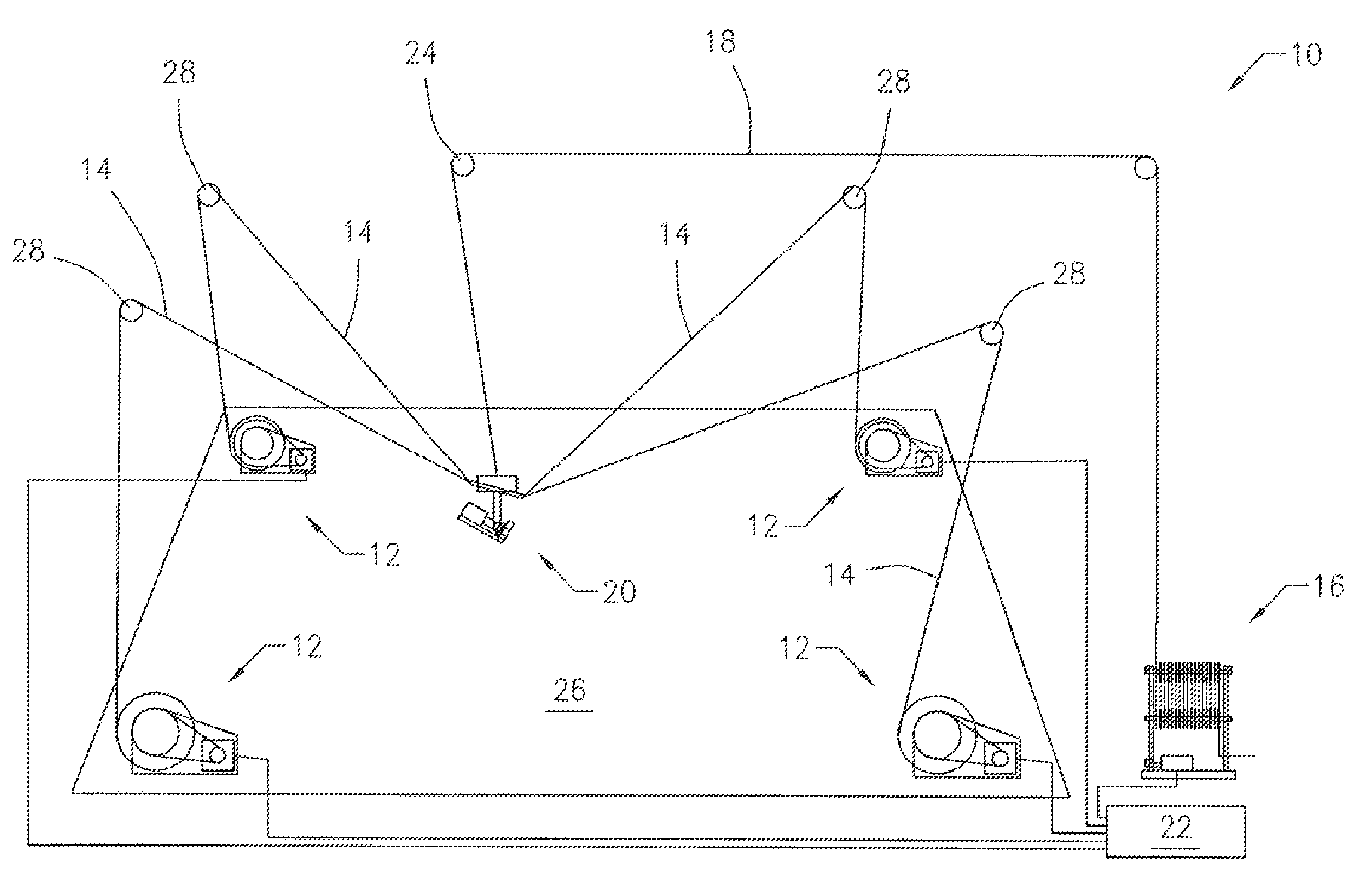
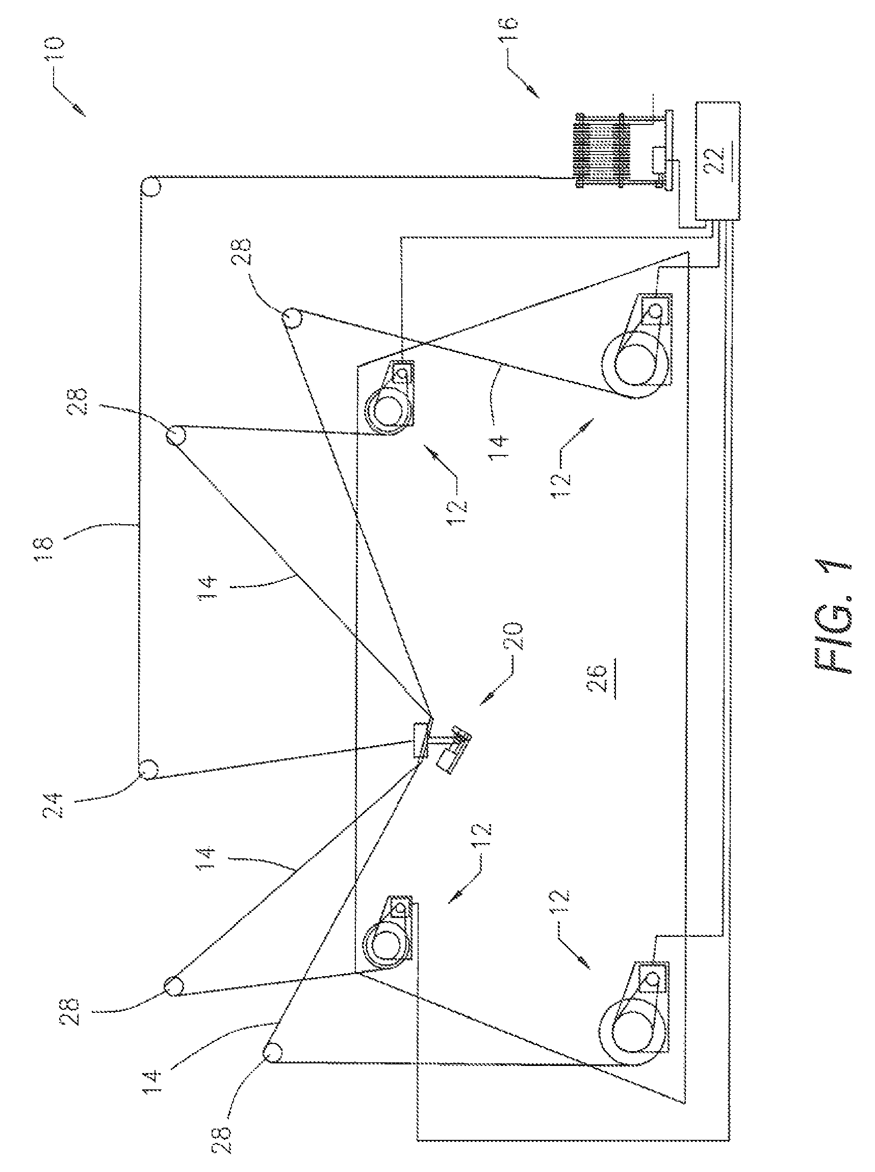
[0046]Referring to the figures of the drawings, wherein like numerals of reference designate like elements throughout the several views, and initially to FIG. 1, an aerial camera system 10 used in broadcast sporting events, film productions and entertainment events such as concerts and awards shows. The aerial camera system 10 includes a plurality main reels 12, a main cable 14 assoc...


PUM


Abstract

An aerial camera system including a plurality of main reels, a camera interface / safety reel and a stabilized camera head. The camera head is supported from main cables from the main reels with a safety reel cable providing power, data and video communication between the camera head and a main computer system. Each of the main reels, the camera interface / safety reel and the camera head are in communication with the main computer system, which controls the feeding and reeling in of the main cables. Further, the computer system controls the feeding and reeling in of the safety reel cable, which typically only follows the camera head as it moves in three-dimensional space, but may in emergency mode support the weight of the camera head and be used to slowly pull the camera head up and out of the way so that it does not interfere with any activity below the flight area. The aerial camera system may also include a level wind assembly that keeps the cables wound on the drum of the main reels and / or the safety reel in a controlled and consistent manner. Furthermore, the camera head of the aerial camera system may use a rotating gimbal assembly with computer controlled leveling motors for keeping the camera head level as the gimbal assembly moves.

Description

CROSS-REFERENCE TO RELATED APPLICATIONS[0001]This application claims priority to U.S. Provisional Application Ser. No. 61 / 030,081, filed Feb. 20, 2008, which is incorporated herein by reference.BACKGROUND OF THE INVENTION[0002]1. Field of the Invention[0003]This invention relates generally to an aerial camera system, and more particularly to an aerial camera system having a computer controlled, powered camera interface / safety reel and a stabilized camera platform for use in broadcast sporting events, film productions and entertainment events, such as concerts and awards shows.[0004]2. Description of the Related Art[0005]Known aerial camera systems encompass two main embodiments to move objects through three-dimensional space. One main type of known aerial camera system utilizes at least two supporting ropes in communication with a camera platform through a series of pulleys. The principal behind these types of aerial camera systems is a technique of relocating or displacing lengths ...

Claims


Application Information

Patent Timeline
Patent Type & Authority Patents(United States)
IPC IPC(8): H04N7/18H04N9/47
CPCF16M11/105F16M11/18F16M11/2064F16M11/425G03B15/006H04N5/2251H04N5/232B66C21/00B66D1/38H04N23/695
Inventor BENNETT, PATRICK J.COOK, GARRETJONES, MATTHEW R.ASHENAYI, KAVEHHENRY, MICHAEL F.MACDONALD, ALEXANDER
Owner SKYCAM
Learn More