Method and system for real time judging boundary lines on tennis court

a tennis court and real-time judging technology, applied in the field of method and system for locating moving objects, can solve the problems of inability to meet the needs of users,

Inactive Publication Date: 2012-06-12
SHLYAK YURIY +1
View PDF17 Cites 47 Cited by
  • Summary
  • Abstract
  • Description
  • Claims
  • Application Information

AI Technical Summary

Benefits of technology

[0016]Accordingly, it is the objective of the present invention to provide a method and a system for real time judging of boundary lines on a tennis court during a tennis game, which avoid the disadvantages of the prior attempts.

Problems solved by technology

Human errors of judging positions of tennis ball relative to boundary lines of court are inevitable.
Both above mentioned systems are not acceptable, because they demand change of standard equipment of the game (tennis ball or surface of court).
Its major complexities have deemed this system unviable.
This system demands quite complex processing of stereo images and needs, evidently, an abundance of video camera's pairs for reliable working (which in turn make it complex and expensive).
The system is very complex, requires large processing power and complicated software, and of course is very expensive (setup and operation cost is up to $50000 a week per court).
This system of course is not affordable for numerous non professional tennis clubs.
But such a system has essential drawbacks.
Then, because of geometry of watching, sudden change of trajectory of the tennis ball, caused by bouncing from court and seen by one or a few video cameras, may be so insignificant in some part of the court, that registration of this change will have low precision and reliability and will be often impossible (in connection with geometry of watching every video camera can have “blind” areas for registration of these changes).
This may lead to higher processing power of computing system and make the described system in whole quite complex and expensive.

Method used


Image

  • Method and system for real time judging boundary lines on tennis court
  • Method and system for real time judging boundary lines on tennis court
  • Method and system for real time judging boundary lines on tennis court

Examples


Embodiment Construction

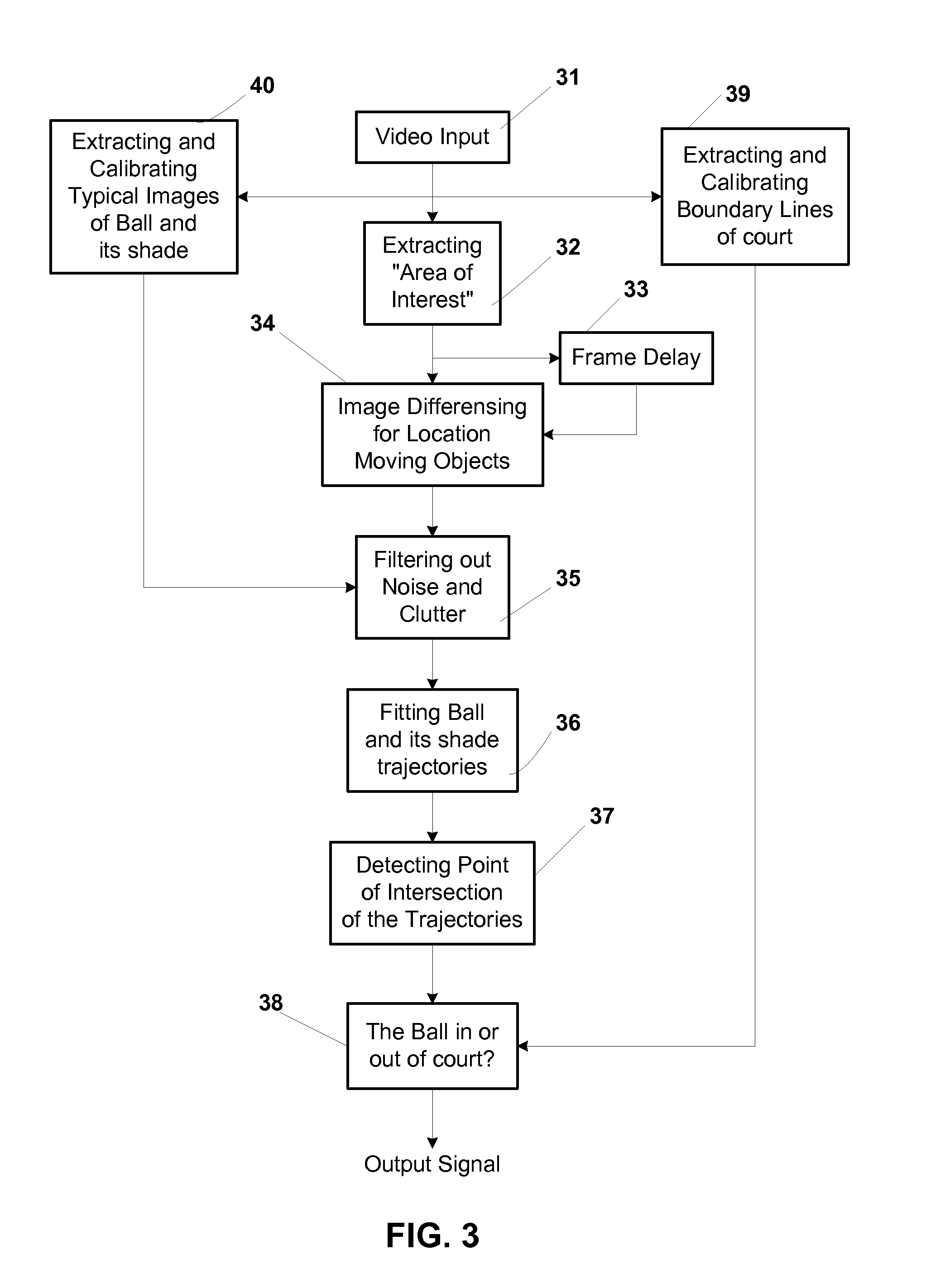
[0030]The present invention will now be described in detail with references to the drawings, which collectively illustrate a method and a system for real time judging boundary lines on a tennis court by location of bouncing points of a tennis ball relative to boundary lines of court according to the present invention.

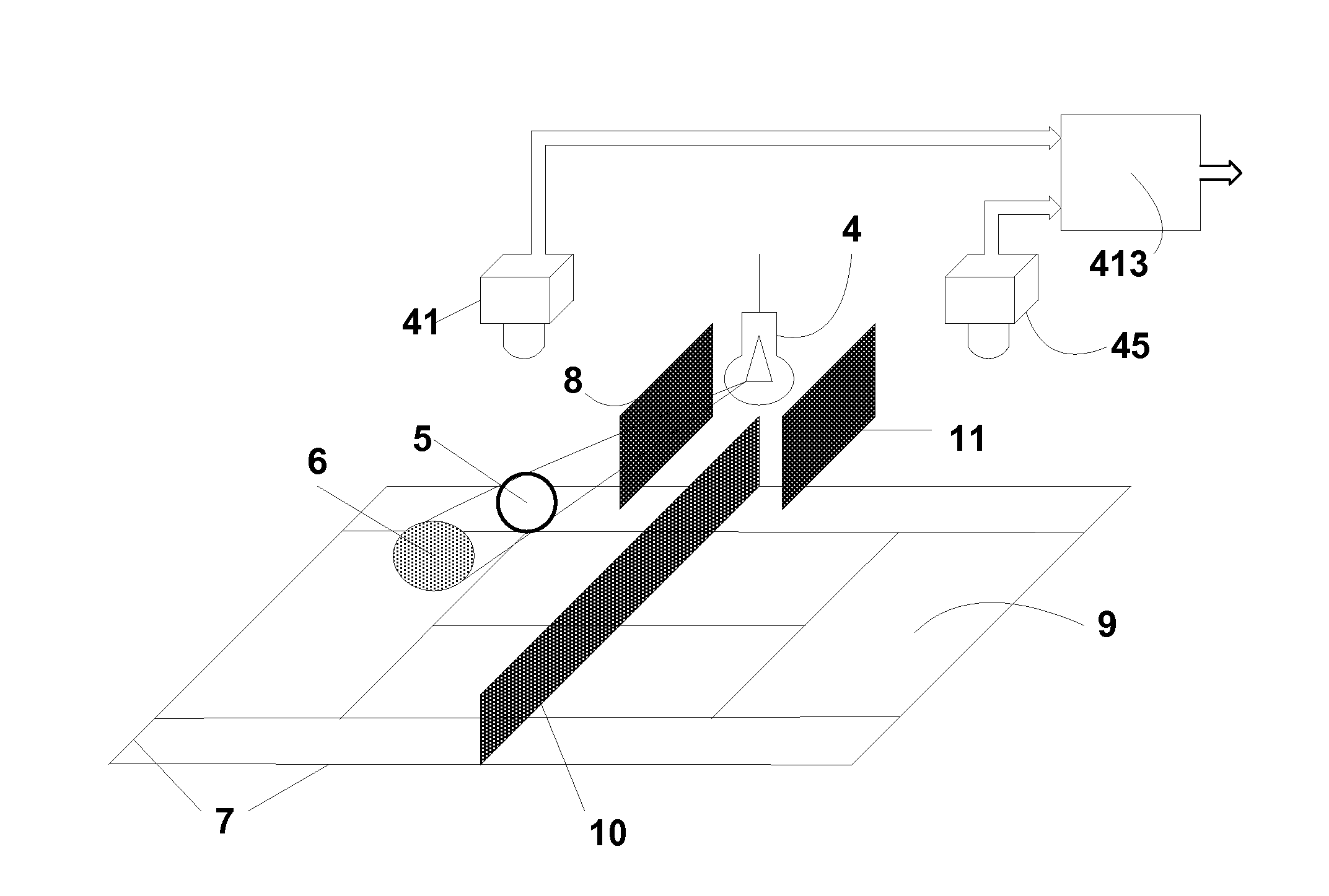
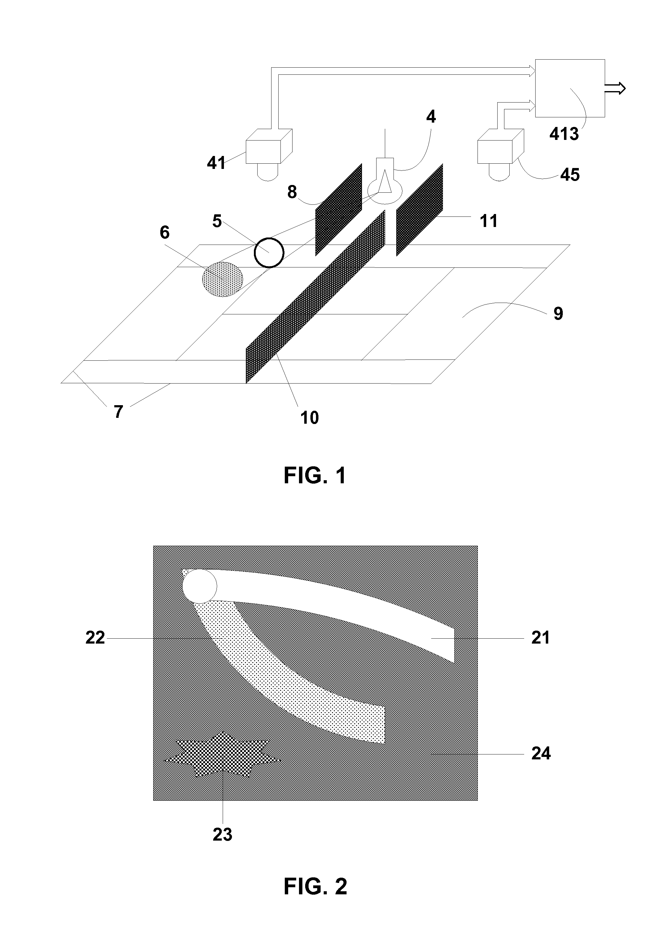
[0031]FIG. 1 shows a perspective view of an embodiment of the method and system on a tennis court.

[0032]In the preferred embodiment two black and white video cameras 41 and 45 are used, where video camera 41 outputs video image of left half of the court 9 and video camera 45 outputs video image of right half of the court 9. The best positions of video cameras 41 and 45 are over the centers of left half of the court and right half of the court correspondingly on the height 5-10 m. One can be used one video camera or more than two, but using two video cameras is the best compromise between price of the system and resolution of the details of the court. Video cameras shoul...


PUM


Abstract

There is provided a method and a system for registration of real time position of tennis ball relatively to boundary lines on tennis court. The method and system comprise sensitive to near-infrared radiation at least one video camera, outputting video image of court and the method and system further include at least one point source of near-infrared radiation, illuminating tennis court and displaced relatively to the video camera. It is suggested a simple and inexpensive way of determining if a tennis ball bounces in or out of court by determining point of intersection of trajectories of the tennis ball and its shade from near-infrared radiation and comparing the position of the determined point of intersection with previously calibrated boundary lines of court.

Description

FIELD OF THE INVENTION[0001]The present invention relates to a method and system for locating moving objects in sporting events, such as tennis, and specifically to real time judging boundary lines on a tennis court by location of bouncing points of a tennis ball relative to boundary lines of the court for automatic officiating of the game.BACKGROUND OF THE INVENTION[0002]Sporting games involving rules around boundaries depend on the decisions of human judges or players themselves (for amateurs). For example, in tennis one needs to trace a position of a relatively small (approximately 6.5 cm in diameter) tennis ball, often traveling at relatively high speed (up to 65 msec) over a relatively large area of tennis court (24 m long by 11 m wide). Human errors of judging positions of tennis ball relative to boundary lines of court are inevitable.[0003]Due to details previously mentioned, it is crucial to build a commercially viable system for automatic judging of boundary lines for tenni...

Claims


Application Information

Patent Timeline
Patent Type & Authority Patents(United States)
IPC IPC(8): H04N7/18
CPCA63B71/0605G06T7/004A63B2071/0611A63B2220/806G06T2207/10048G06T2207/10016G06T2207/30224G06T2207/30241G06T7/70
Inventor SHLYAK, YURIYKOMAROV, VLADIMIR
Owner SHLYAK YURIY
Why Eureka
Try Eureka