Field-based asset management device and architecture

a technology of asset management and field-based asset, applied in the direction of total factory control, programme control, instruments, etc., can solve the problems of critical process and complex control of industrial plants

Active Publication Date: 2012-06-12
FISHER-ROSEMOUNT SYST INC
View PDF15 Cites 17 Cited by
  • Summary
  • Abstract
  • Description
  • Claims
  • Application Information

AI Technical Summary

Problems solved by technology

Control of an industrial plant is a very complex and critical process.

Method used


Image

  • Field-based asset management device and architecture
  • Field-based asset management device and architecture
  • Field-based asset management device and architecture

Examples


Embodiment Construction

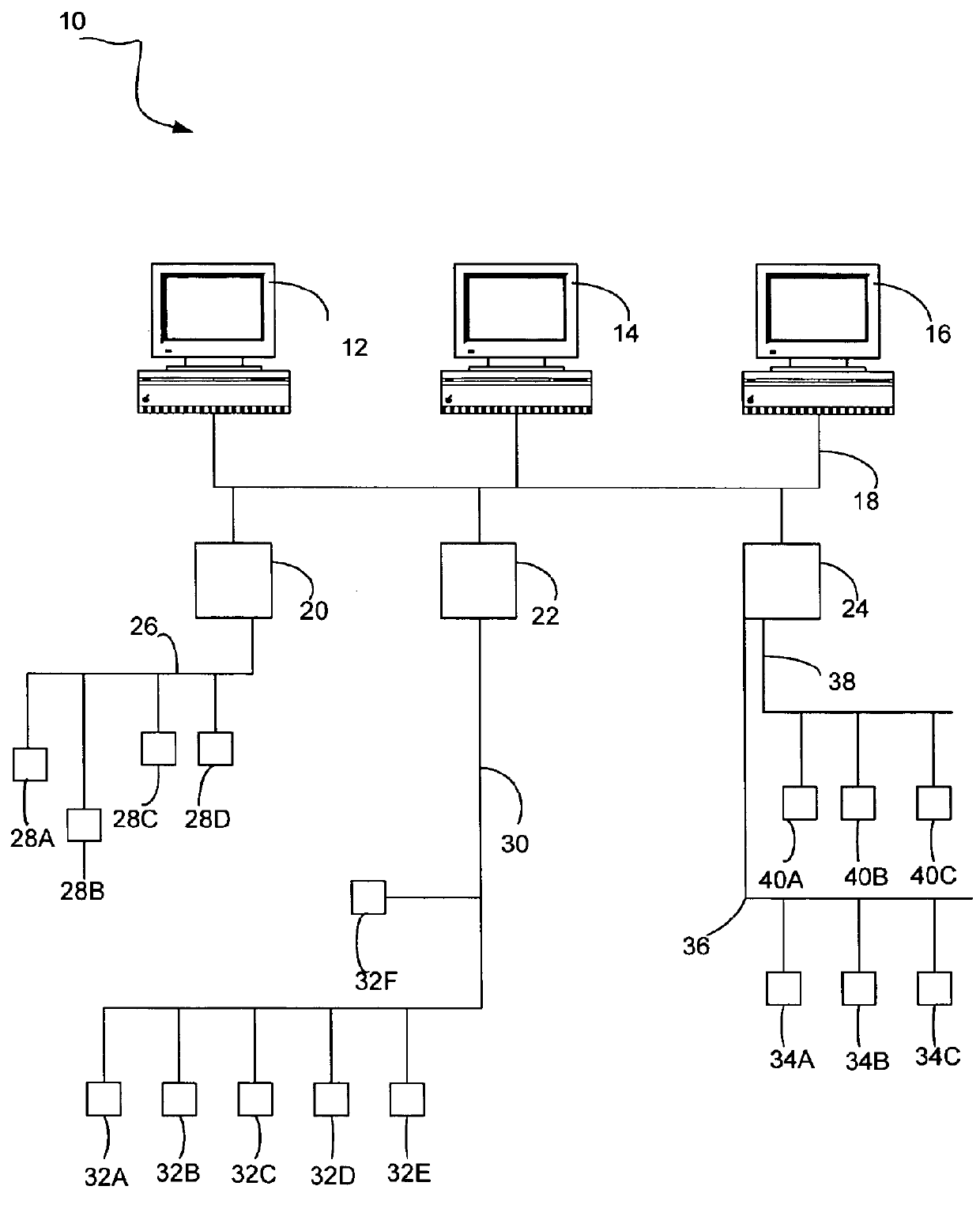
[0016]FIG. 1 is a diagrammatic view of a process control and measurement installation in accordance with the prior art. System 10 includes a plurality of workstations 12, 14, 16 coupled together via a local area network, such as an Ethernet network 18. A plurality of field device multiplexers 20, 22, 24 are also coupled to Ethernet local area network (LAN) 18. Each of multiplexers 20, 22, 24 is a known device that is able to interface between a process industry standard communication network and local area network 18. For example, multiplexer 20 is a HART® multiplexer that is able to interface between HART® communication loop 26 and LAN 18. Thus, field devices 28A, 28B, 28C, 28D, which are coupled to HART® communication loop 26 are accessible, to one degree or another, to workstation 12, 14, 16 via interface device 20. Similarly, multiplexer device 22 is an interface between LAN 18 and Hi FOUNDATION™ Fieldbus process communication segment 30. Thus, fieldbus devices 32A, 32B, 32C, 32...


PUM


Abstract

A field mountable interface module is provided. The intelligent interface module includes at least one data connection port configured to couple to a data communication network as well as at least one process communication connection port configured to couple to a field device bus. The intelligent interface module also includes a controller and memory coupled to the controller. The controller is configured to provide a higher order function with respect to one or more field devices and / or field device buses. Higher order functions include calibration support, complex device support, diagnostic support, distributed control system support, and virtual field device functions.

Description

CROSS-REFERENCE TO RELATED APPLICATION[0001]The present application is based on and claims the benefit of U.S. provisional patent application Ser. No. 60 / 706,626, filed Aug. 9, 2005, the content of which is hereby incorporated by reference in its entirety.BACKGROUND OF THE INVENTION[0002]Process monitoring and control systems, such as those used in chemical processes, petroleum, or other types of industrial processes, typically include a centralized monitoring and control system communicatively coupled to a workstation of an operator or a user and to one or more field devices via analog or digital communication paths. Field devices can include sensors adapted to monitor processor parameters (such as temperature, pressure, flow rate, and the like) and / or actuators adapted to perform operations on the industrial process (such as opening and closing valves, and so on).[0003]Generally, the centralized monitoring and control system receives signals indicative of process measurements made...

Claims


Application Information

Patent Timeline
Patent Type & Authority Patents(United States)
IPC IPC(8): G06F15/16
CPCG05B19/0426G05B19/4185H04L12/2602H04L43/00G05B2219/24048G05B2219/24056G05B2219/25428G05B2219/31124G05B2219/31129G05B2219/34444H04L2012/4026Y02P90/02Y02P90/80
Inventor ERYUREK, EVRENSCHUMACHER, MARK S.PELUSO, MARCOSKARSCHNIA, ROBERT J.WELLS, CHRISTOPHER
Owner FISHER-ROSEMOUNT SYST INC
Why Eureka
Try Eureka