
Adjusting device for a headrest of a motor vehicle seat

a technology for motor vehicles and headrests, which is applied in the direction of chairs, pedestrian/occupant safety arrangements, instruments, etc., can solve problems such as head and neck injuries, and achieve the effect of reducing the speed of travel and optimal adjustment of the headrests

Active Publication Date: 2012-06-19
BROSE FAHRZEUGTEILE GMBH & CO KG
View PDF18 Cites 39 Cited by
  • Summary
  • Abstract
  • Description
  • Claims
  • Application Information

AI Technical Summary

Benefits of technology

The solution reliably avoids system-caused misadjustments by accurately determining the headrest's position relative to the occupant's head, ensuring the headrest is correctly aligned to minimize injury risk during crashes, and allows for precise and rapid adjustment without overshooting the target position.

Problems solved by technology

However, the increase in safety achieved through the headrest is only realized to its full extent when the headrest is adjusted to the right height relative to the head's vertical position, so that in the event of a crash the head essentially strikes a center of the headrest provided for this purpose.
In contrast, an incorrectly adjusted headrest can result in injuries to the head and neck region in the event of a crash.

Method used


Image

  • Adjusting device for a headrest of a motor vehicle seat
  • Adjusting device for a headrest of a motor vehicle seat
  • Adjusting device for a headrest of a motor vehicle seat

Examples


first embodiment

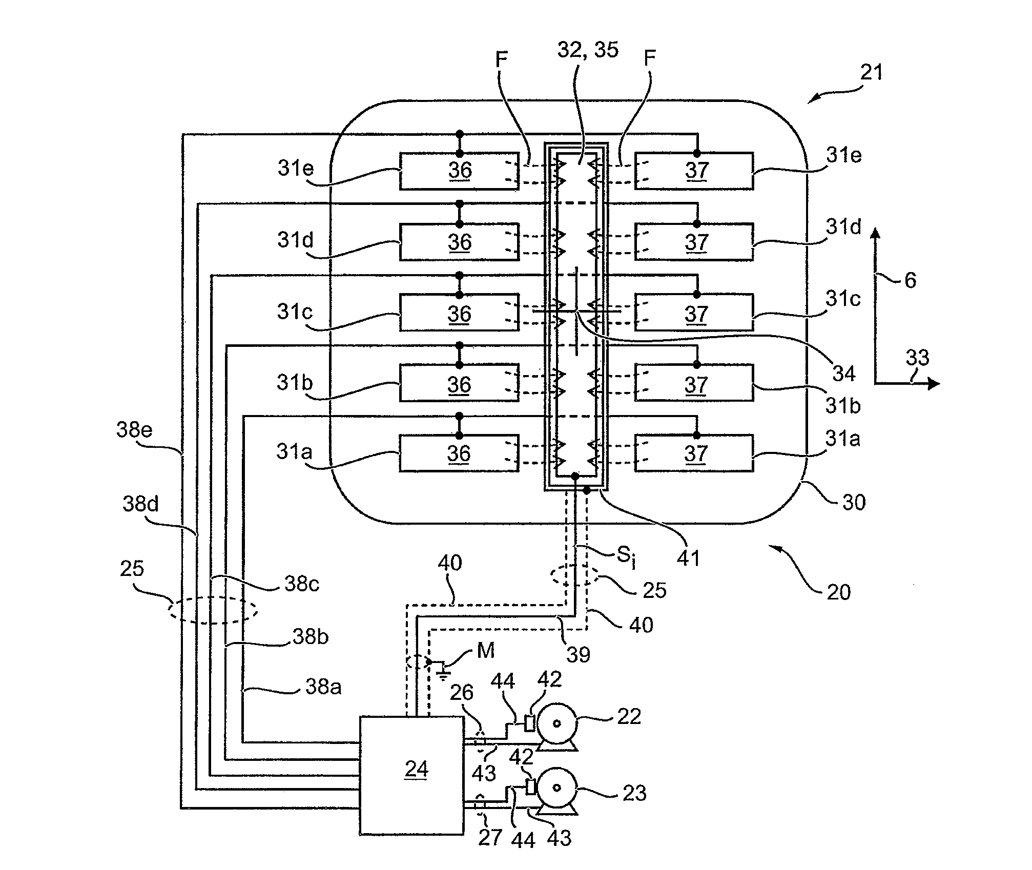
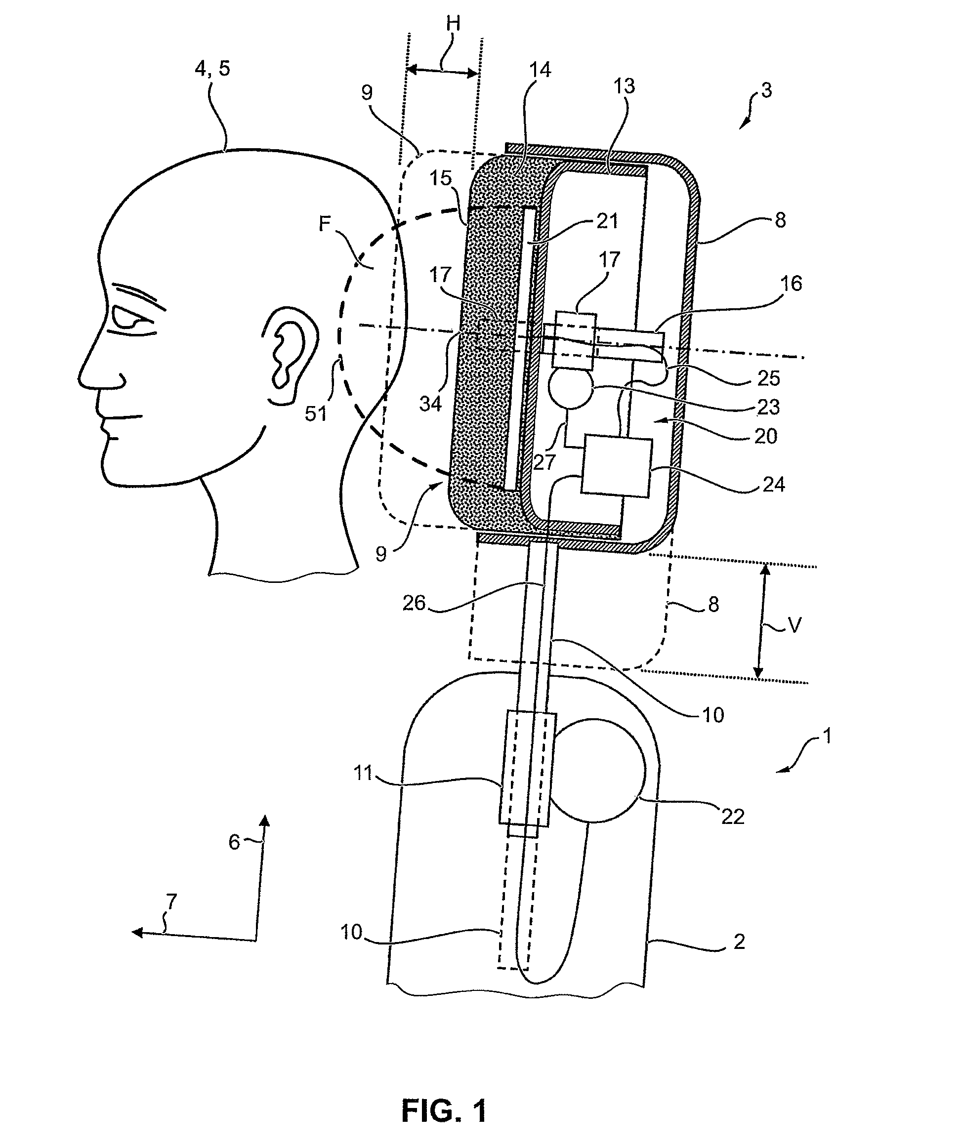
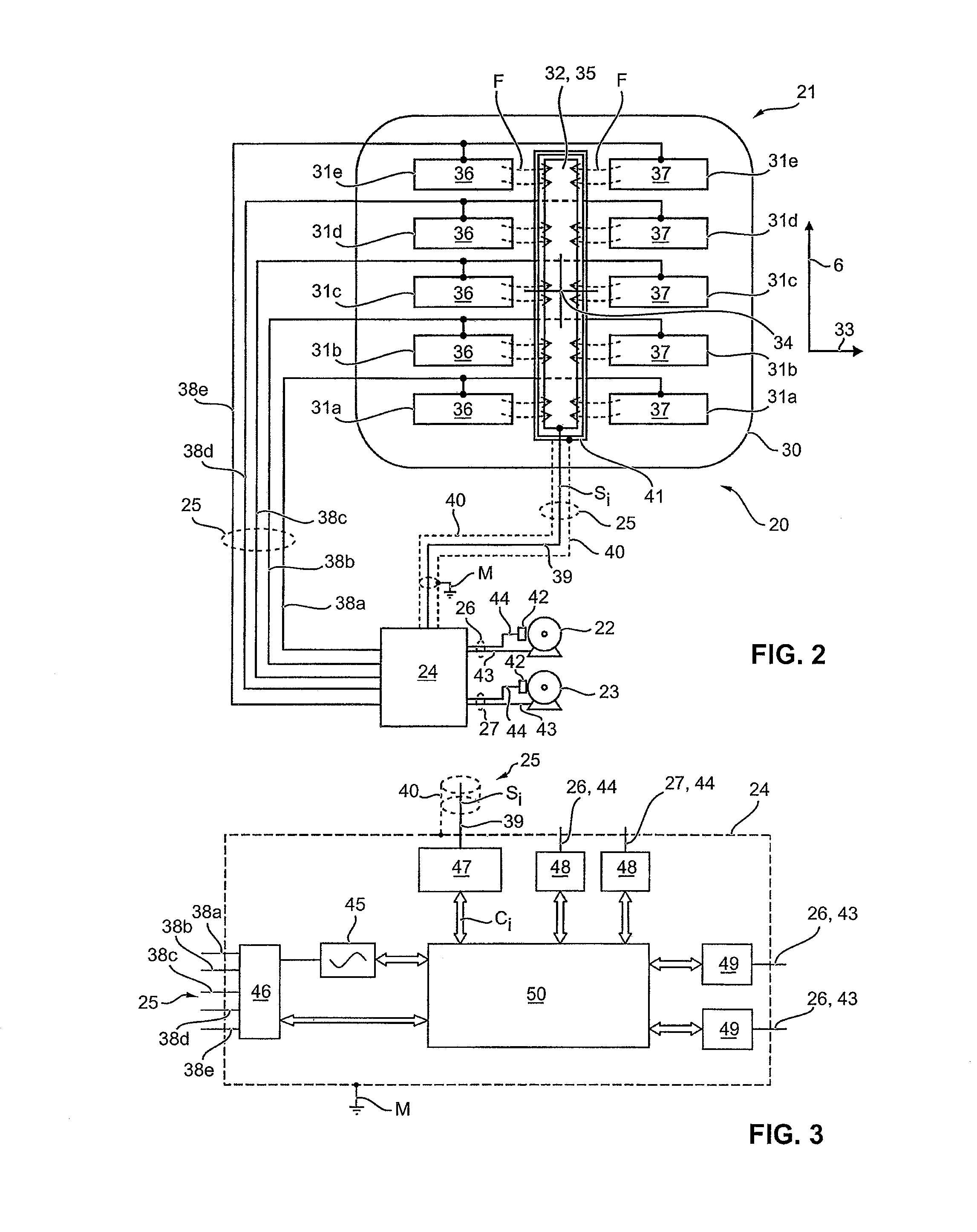
[0054]FIG. 2 shows the adjusting device 20 in greater detail. As is evident from this representation in combination with FIG. 1, the proximity sensor 21 comprises a flat carrier 30. Mounted on the carrier is an electrode arrangement consisting of five transmitting electrodes 31a to 31e, and a common receiving electrode 32. The carrier 30 is made of a plastic film, preferably flexible. The electrodes 31a to 31e and 32 are made of metal films, preferably also flexible, which are, e.g., glued onto the carrier 30. Alternatively, the electrodes 31a to 31e and 32 can also be applied to the carrier 30 in the form of a coating.

[0055]The carrier 30 extends over a primarily flat region of the headrest 3 in both the vertical direction 6 and a vehicle direction 33 transverse thereto. In particular, the carrier 30 is located approximately centered on a center 34 of the headrest 3 on which the head 4 is intended to impact in the case of a crash.

[0056]The electrodes 31a to 31e and 32 are in turn d...

second embodiment

[0078]FIG. 8 shows the adjusting device 20. Except as otherwise described below, this embodiment is the same as the embodiment of the adjusting device 20 described in conjunction with FIG. 2. However, in place of the transmitting electrodes 31a to 31e there, according to FIG. 8 five receiving electrodes 60a to 60e are provided—with the same geometric arrangement of electrode areas 36 and 37 on the carrier 30. In place of the receiving electrode 32 from the embodiment according to FIG. 2, according to FIG. 8 a common transmitting electrode 61—with the same geometric arrangement of the associated electrode area 35—is provided. A shielding of the individual line 39 is not required here. The guard electrode 41 shown in FIG. 2 can likewise be omitted. In its place, the individual lines 38a to 38e, which connect the control unit 24 to the receiving electrodes 60a to 60e here, are preferably electrically shielded—in particular individually. A suitable shield 53 is indicated schematically i...


PUM


Abstract

An adjusting device for a headrest of a motor vehicle seat is specified. The adjusting device comprises, in a first variant, a capacitive proximity sensor integrated into or designed for integration into the headrest having at least three transmitting electrodes spaced apart vertically from one another and having a common receiving electrode. In a second variant of the adjusting device, the proximity sensor has at least three receiving electrodes spaced apart vertically from one another and has a common transmitting electrode. In both variants, the adjusting device also has an actuating drive for motorized vertical adjustment of the headrest relative to the vehicle seat, as well as a control unit. The control unit here is designed to drive the transmitting electrodes or transmitting electrode for emission of an alternating electric field to determine from the received electrical signals detected from the receiving electrode or the receiving electrodes, respective associated measured capacitance values that contain information about the capacitance produced between each of the transmitting electrodes or receiving electrodes and the common receiving electrode or transmitting electrode, and to drive the actuating drive to establish a vertical target position of the headrest relative to the head position of a vehicle occupant as a function of the measured capacitance values.

Description

[0001]This nonprovisional application claims priority under 35 U.S.C. §119(a) to German Patent Application No. 10 2008 064 348.3, which was filed in Germany on Dec. 20, 2008, and which is herein incorporated by reference.BACKGROUND OF THE INVENTION[0002]1. Field of the Invention[0003]The invention relates to an adjusting device for a headrest of a motor vehicle seat.[0004]2. Description of the Background Art[0005]A headrest in a motor vehicle seat typically serves to support the head of a vehicle occupant using the seat in the event of a crash, thereby avoiding rearward bending of the cervical spine. However, the increase in safety achieved through the headrest is only realized to its full extent when the headrest is adjusted to the right height relative to the head's vertical position, so that in the event of a crash the head essentially strikes a center of the headrest provided for this purpose. In contrast, an incorrectly adjusted headrest can result in injuries to the head and n...

Claims


Application Information

Patent Timeline
Patent Type & Authority Patents(United States)
IPC IPC(8): B60N2/42
CPCB60N2/002B60N2/4829B60N2/4885B60N2/4864B60N2002/0268B60N2/888B60N2/829B60N2/865B60N2/0268B60N2220/20B60N2/0028B60N2210/12B60N2/003B60N2210/14
Inventor WUERSTLEIN, HOLGERHOFMANN, TOBIASKHEMIRI, FAOUZI
Owner BROSE FAHRZEUGTEILE GMBH & CO KG
Learn More