Fluid pressure sensing chamber

a technology of fluid pressure and sensing chamber, which is applied in the direction of positive displacement liquid engines, instruments, machines/engines, etc., can solve the problems of air bubbles that are extremely difficult to purge from the system, undesirable pressure variations and fluctuations, and vision deterioration, etc., and achieve the effect of easy prim

Active Publication Date: 2012-06-19
ALCON INC
View PDF82 Cites 26 Cited by
  • Summary
  • Abstract
  • Description
  • Claims
  • Application Information

AI Technical Summary

Benefits of technology

[0010]One objective of the present invention is to provide a cassette a pressure sensing chamber that is easy to prime.

Problems solved by technology

When age or disease causes the lens to become less transparent, vision deteriorates because of the diminished light which can be transmitted to the retina.
Compliance results in undesirable pressure variations and fluctuations.
The inventors of the present invention have discovered that the initial priming of a pressure sensor chambers found within closed surgical fluidic systems is relatively easy, but if bubbles of air are allowed to enter the chamber (for example, if the surgical handpiece is changed mid-procedure), these air bubbles are extremely difficult to purge from the system.
This difficulty is the result of the surface tension of the air bubble (as opposed to the unencapsulated air generally involved in the initial priming of the system) causing the bubble to be relatively robust and not easily broken and drawn out of the pressure sensing chamber once introduced.
In addition, the liquid “film” surrounding the air bubble is tacky, causing the bubble to stick or adhere to surfaces within the system and resist further movement, even with very high flow rates.
The inventors have found that the chamber shapes and designs discussed in this reference are insufficient to assure that air bubbles can be purged from the system.

Method used


Image

  • Fluid pressure sensing chamber
  • Fluid pressure sensing chamber
  • Fluid pressure sensing chamber

Examples


Embodiment Construction

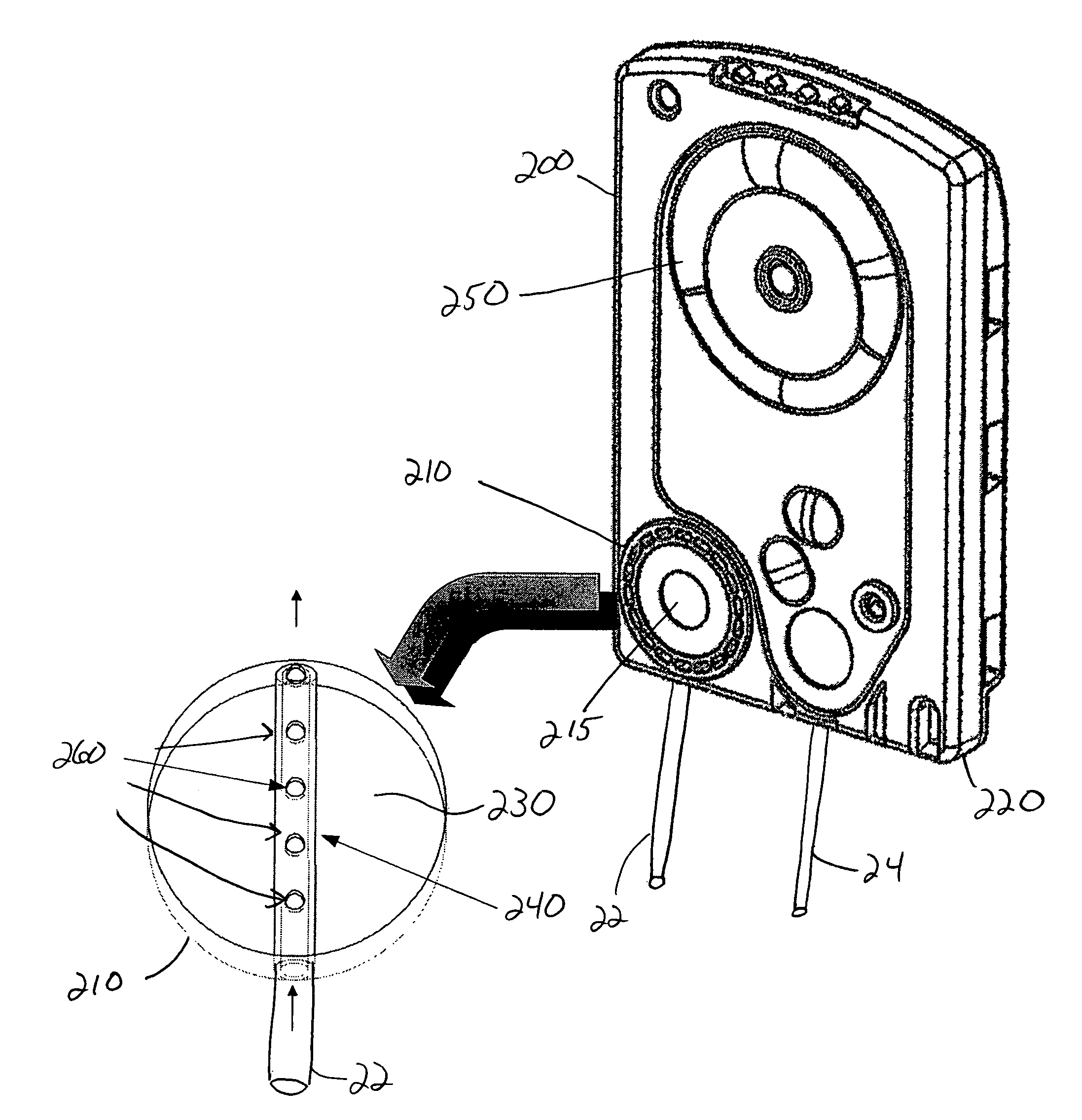
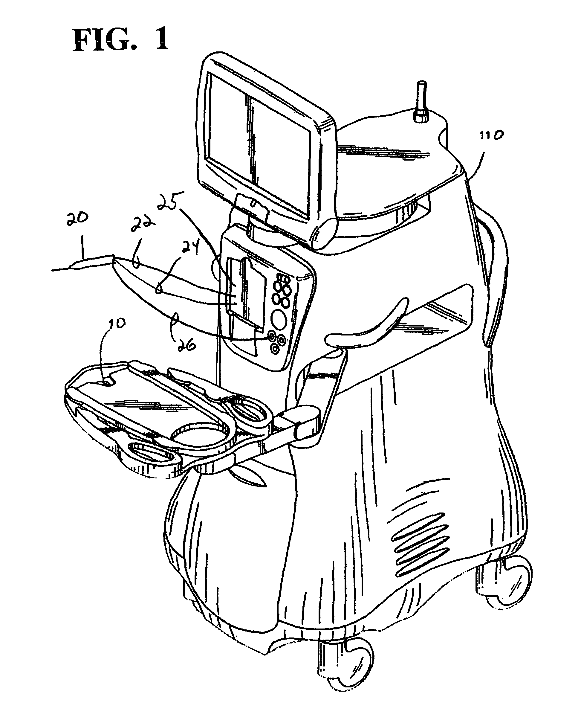
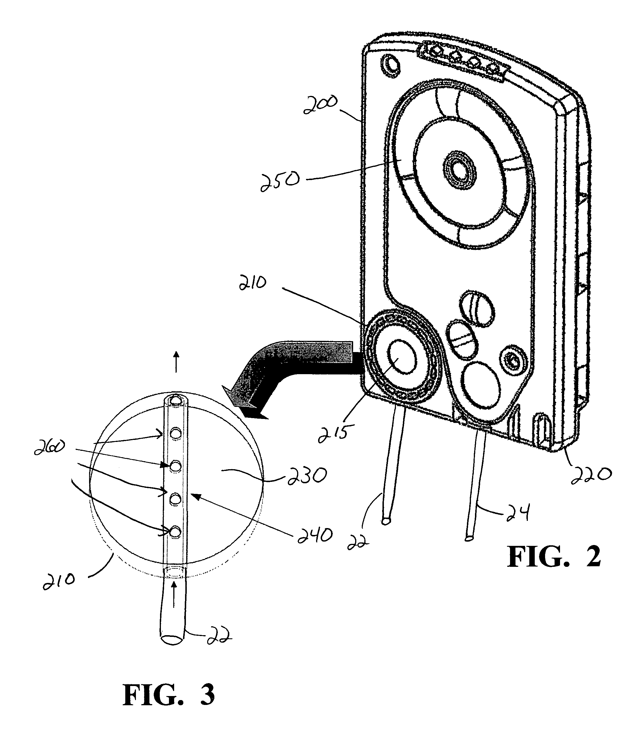
[0017]As best seen in FIG. 1, commercially available surgical systems generally include surgical console 110 having attached, adjustable mayo tray 10 and handpiece 20 attached to console 110 by aspiration tubing 22, irrigation tubing 24 and power cable 26. Power to handpiece 20 as well as the flows of irrigation and aspiration fluid is controlled by console 110, which contains appropriate hardware and software, such as power supplies, pumps, pressure sensors, valves, all of which are well-known in the art. As best seen in FIG. 2, cassette 200 that may be used with the present invention receives aspiration tubing 22 and irrigation tubing 24 and is installed within cassette receiving portion 25 of console 110. Cassette 200 contains a pressure sensing chamber 210 which may consist of hollow void 230 formed within body 220 of cassette 200 and enclosed by pressure sensing diaphragm 215. Cassette 200 may be any of a variety of commercially available surgical cassettes such as the INFINITI...


PUM


Abstract

A pressure sensing chamber having a tubing extension extending through the chamber. The tubing contains a plurality of ports so as to allow the purging of air from the chamber, but the ports are sized so that bubbles entering the tubing cannot easily flow into the chamber.

Description

BACKGROUND OF THE INVENTION[0001]The present invention relates generally to fluid pressure sensing chambers and more specifically to fluid pressure sensing chambers used in ophthalmic surgical equipment.[0002]When age or disease causes the lens to become less transparent, vision deteriorates because of the diminished light which can be transmitted to the retina. This deficiency in the lens of the eye is medically known as a cataract. An accepted treatment for this condition is surgical removal of the lens and replacement of the lens function by an artificial intraocular lens (IOL).[0003]In the United States, the majority of cataractous lenses are removed by a surgical technique called phacoemulsification. During this procedure, a thin phacoemulsification cutting tip is inserted into the diseased lens and vibrated ultrasonically. The vibrating cutting tip liquefies or emulsifies the lens so that the lens may be aspirated out of the eye. The diseased lens, once removed, is replaced by...

Claims


Application Information

Patent Timeline
Patent Type & Authority Patents(United States)
IPC IPC(8): A61M31/00F04B43/12
CPCA61M1/0058A61M1/0027A61F9/00736A61M1/0066A61M2205/12A61M2205/3331A61M1/732A61M1/80A61M1/77A61M3/0201A61M1/72G01N31/00G01N33/00G01N35/00
Inventor MORGAN, MICHAEL D.
Owner ALCON INC
Why Eureka
Try Eureka