Yaw bearing system

a technology of yaw bearings and wind energy, which is applied in the direction of mechanical equipment, machines/engines, electric generator control, etc., can solve the problems of high warranty cost and possible consequences for lower customer satisfaction

Active Publication Date: 2012-06-19
GENERAL ELECTRIC CO
View PDF51 Cites 11 Cited by
  • Summary
  • Abstract
  • Description
  • Claims
  • Application Information

AI Technical Summary

Problems solved by technology

Current bed plate designs could possibly identify fatigue problems, especially near the yaw bearing where the forces and the moments have a maximum.
Higher warranty costs and lower customer satisfaction are possible consequences.

Method used


Image

  • Yaw bearing system
  • Yaw bearing system
  • Yaw bearing system

Examples


Embodiment Construction

[0019]Reference will now be made in detail to the various embodiments of the invention, one or more examples of which are illustrated in the figures. Each example is provided by way of explanation of the invention, and is not meant as a limitation of the invention. For example, features illustrated or described as part of one embodiment can be used on or in conjunction with other embodiments to yield yet a further embodiment. It is intended that the present invention includes such modifications and variations.

[0020]Within the following description of the drawings, the same reference numbers refer to the same components. Generally, only the differences with respect to the individual embodiments are described. The structures shown in the drawings are not depicted true to scale but rather serve only for the better understanding of the embodiments.

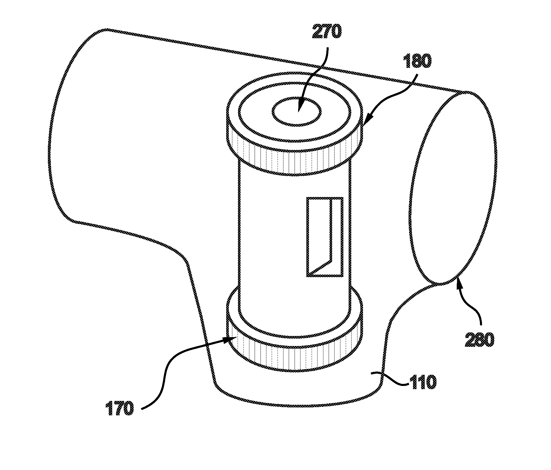
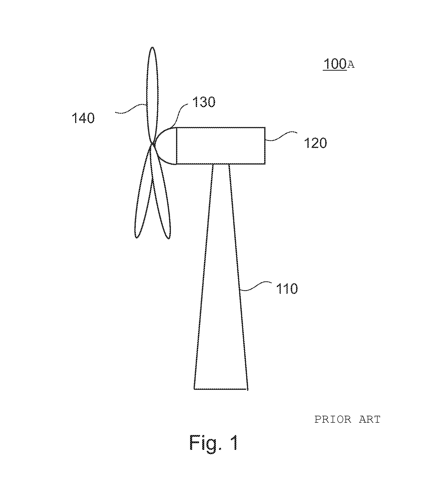
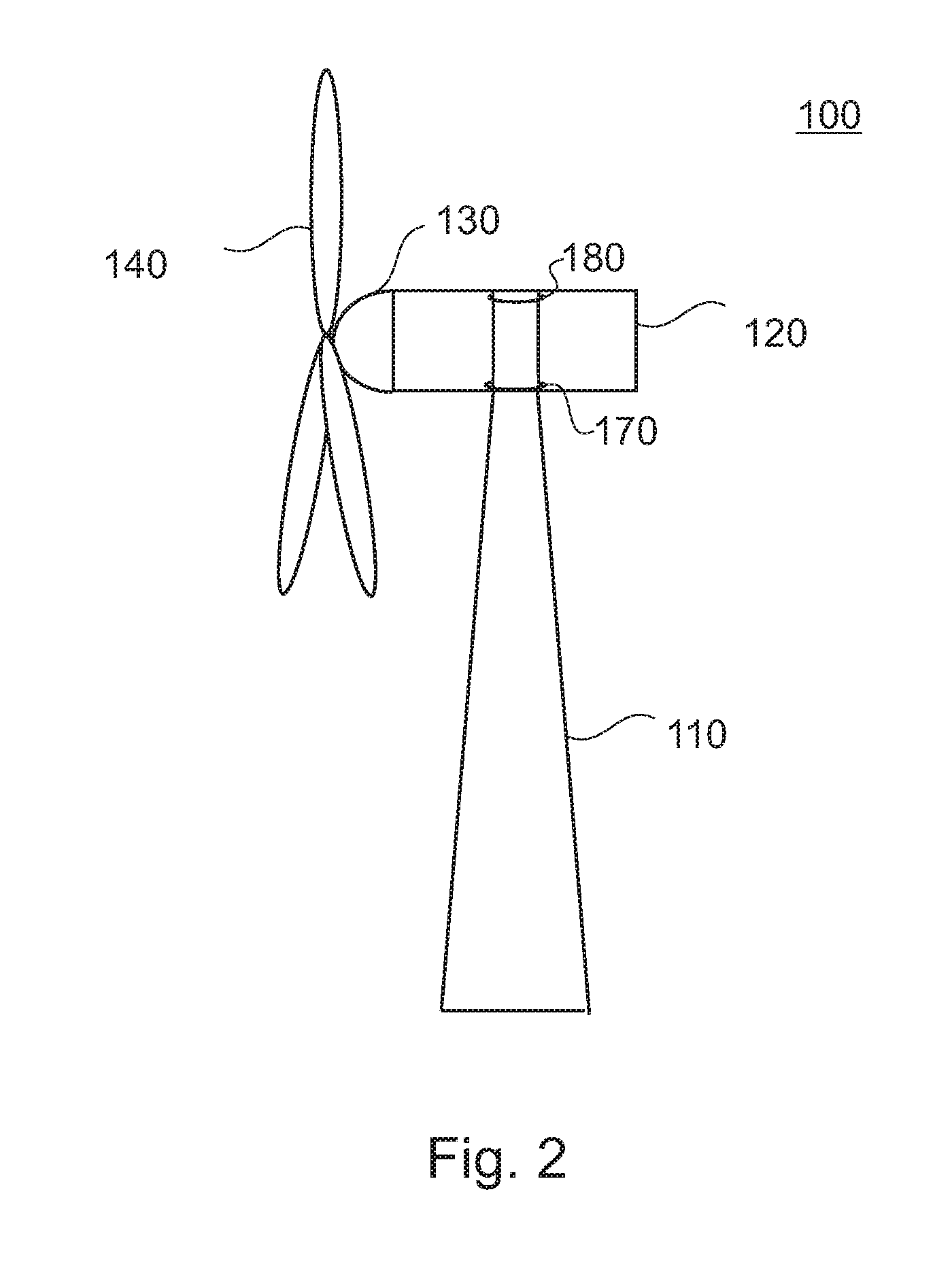
[0021]FIG. 1 is a schematic view of a wind energy system 100A, also referred to as a wind turbine. The wind energy system 100A includes a tow...


PUM


Abstract

A wind energy system is provided, with the wind energy system having a tower; a machine nacelle; a lower yaw bearing; and an upper yaw bearing; the lower yaw bearing and the upper yaw bearing being arranged to pivotably connect the machine nacelle to the tower of the wind energy system. Further, a yaw bearing system for use in a wind energy system and a method for operating a wind energy system are provided.

Description

BACKGROUND OF THE INVENTION[0001]The present disclosure relates to a wind energy system and a yaw bearing system for a wind energy system.[0002]Forces and moments from a drive train of a wind energy system to the tower of the wind energy system are guided by a large yaw bearing. The yaw bearing is usually one large wheel with teeth pointing outwards or inwards depending on the location of the yaw drive. The yaw drive is used to orientate the machine nacelle with the drive train relative to the tower.[0003]Wind energy systems have a nacelle with a bed plate fixed therein. The bed plate is connected to the yaw bearing. Current bed plate designs could possibly identify fatigue problems, especially near the yaw bearing where the forces and the moments have a maximum. Higher warranty costs and lower customer satisfaction are possible consequences. Thus, the connection of the nacelle to the tower of the wind energy system should be improved to reduce fatigue problems, especially with futu...

Claims


Application Information

Patent Timeline
Patent Type & Authority Patents(United States)
IPC IPC(8): F03D9/00H02P9/04
CPCF03D11/0008F05B2240/40Y02E10/726Y02E10/722F05B2240/50F03D80/70Y02E10/72F03D7/0204
Inventor HENNIG, JENS
Owner GENERAL ELECTRIC CO
Why Eureka
Try Eureka