
Broadband filter

a filter and band band technology, applied in the field of broadband filters, can solve the problems of inability to filter high frequency noise, interference with other devices, and the inability of the filter b>10/b> to effectively filter noise with limited filtering bands

Active Publication Date: 2012-06-19
HONG FU JIN PRECISION IND (SHENZHEN) CO LTD +1
View PDF8 Cites 8 Cited by
  • Summary
  • Abstract
  • Description
  • Claims
  • Application Information

AI Technical Summary

Benefits of technology

The broadband filter effectively suppresses noise across a wide frequency range, minimizing interference and enhancing the performance of three-phase AC power systems by allowing both low and high frequency noise to be filtered simultaneously.

Problems solved by technology

However, when three-phase AC powers are powered on / off, noise may be generated and transmitted to conductive wires, resulting in interference with other devices, usually loads, connected thereto.
Such noise often includes differential-mode noise generated between live wires and neutral wires and common-mode noise generated between live wires and ground wires and between neutral wires and ground wires.
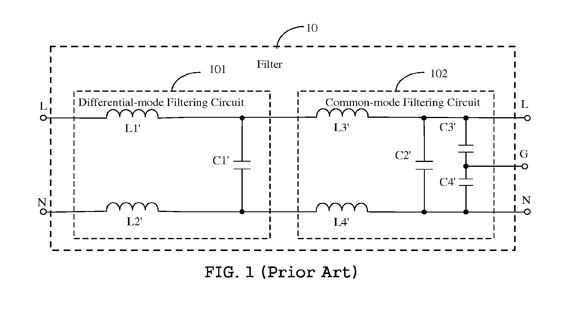
However, capacitors have different equivalent series inductance and different equivalent series resistance during using, which resulting in that capacitors for filtering low frequency noise cannot filter high frequency noise and capacitors for filtering high frequency noise cannot filter low frequency noise.
Thus, the filter 10 cannot effectively filter noise with limited filtering bands.

Method used


Image

  • Broadband filter
  • Broadband filter
  • Broadband filter

Examples


Embodiment Construction

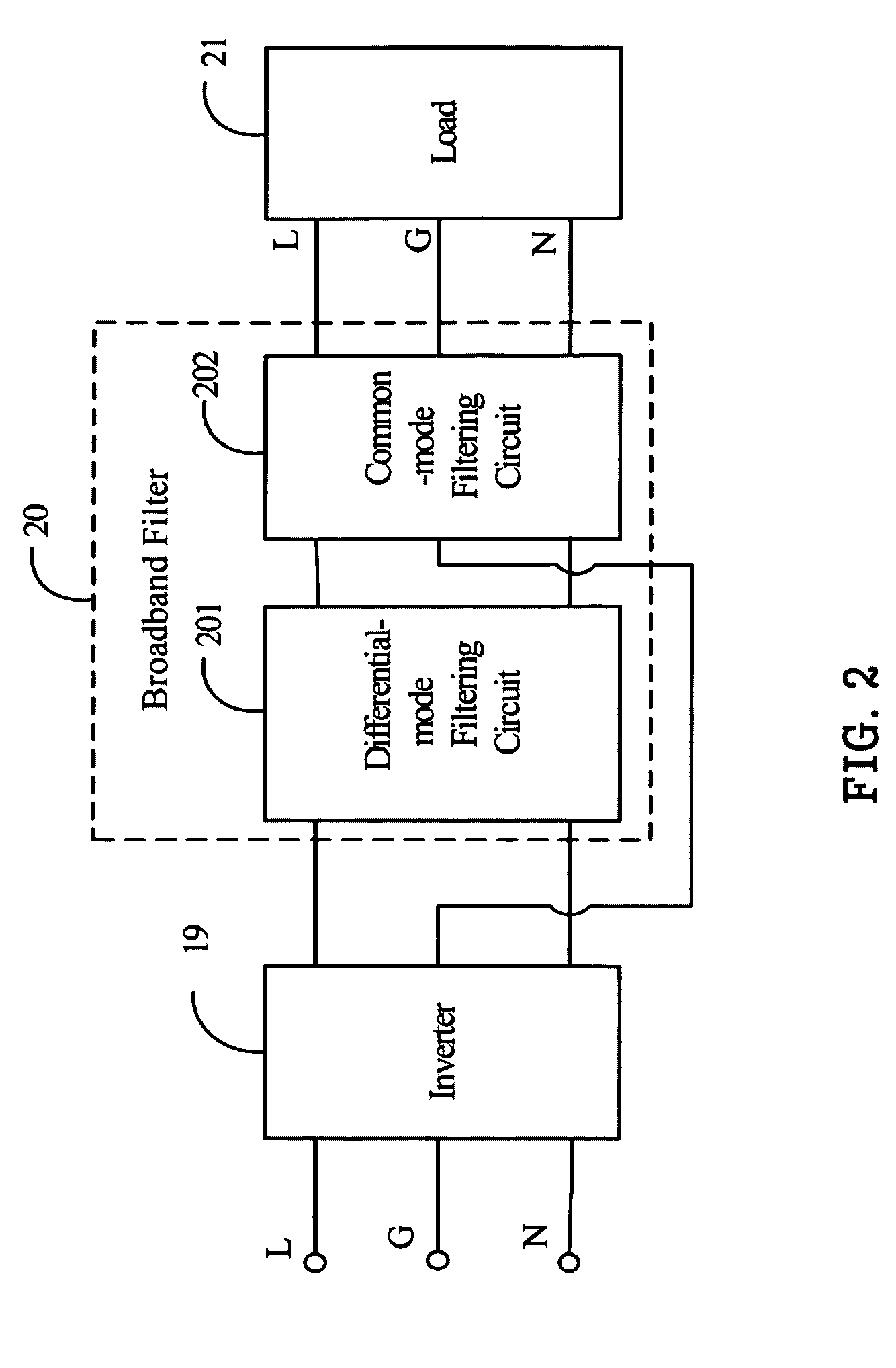
[0011]FIG. 2 is a schematic diagram of one embodiment of an application environment of the disclosed broadband filter 20. An inverter 19, the broadband filter 20, and a load 21 are connected in series through a first conductive wire, a second conductive wire, and a third conductive wire. The inverter 19 outputs signals with noise to the broadband filter 20 to filter the noise, and then the broadband filter 20 outputs the signals without noise to the load 21. The broadband filter 20 includes a differential-mode filtering circuit 201 and a common-mode filtering circuit 202. It is appreciated that the load 21 may be a manufacturing or testing device. The first, second, and third conductive wires are a live wire L, a neutral wire N, and a ground wire G, respectively.

[0012]The differential-mode filtering circuit 201 is structured and arranged to filter differential-mode noise. The common-mode filtering circuit 202 is structured and arranged to filter common-mode noise.

[0013]FIG. 3 is a c...


PUM


Abstract

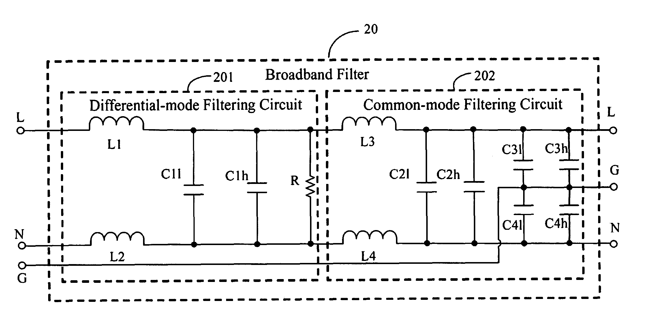
A broadband filter filtering noise over a first conductive wire, a second conductive wire, and a third conductive wire includes a differential-mode filtering circuit connected to both the first conductive wire and the second conductive wire and a common-mode filtering circuit connected to both the first conductive wire and the second conductive wire. The differential-mode filtering circuit includes two inductors and two capacitors for filtering differential-mode noise of different frequencies. The common-mode filtering circuit includes two inductors and six capacitors filtering common-mode noise of different frequencies.

Description

BACKGROUND[0001]1. Technical Field[0002]The disclosure relates to broadband filters.[0003]2. Description of Related Art[0004]Three-phase AC powers are frequently used in manufacturing and conducting applications due to their favorable power generation, electrical distribution, and electrical to mechanical energy conversion characteristics. However, when three-phase AC powers are powered on / off, noise may be generated and transmitted to conductive wires, resulting in interference with other devices, usually loads, connected thereto. Such noise often includes differential-mode noise generated between live wires and neutral wires and common-mode noise generated between live wires and ground wires and between neutral wires and ground wires. Thus, there is a need for filters between the three-phase AC powers and loads for suppressing noise.[0005]FIG. 1 is a circuit diagram of a filter 10 including a live wire L, a neutral wire N, a ground wire G, a differential-mode filtering circuit 101...

Claims


Application Information

Patent Timeline
Patent Type & Authority Patents(United States)
IPC IPC(8): H03H7/00H02M1/12
CPCH02M1/126Y02B70/1483Y02B70/10
Inventor CHEN, HE-PINGHUNG, KUO-WEIKANG, HONG-HAO
Owner HONG FU JIN PRECISION IND (SHENZHEN) CO LTD
Learn More