Multi-needle multi-parallel nanospray ionization source for mass spectrometry

a mass spectrometry and nanospray technology, applied in the field of nanoelectrospray ionization sources, can solve the problems of difficult production of sprays, interference in the detection and quantification of analytes, and difficult handling, and achieves high ionization efficiency, simple manufacturing, and robust multi-sprayer devices.

Active Publication Date: 2012-06-26
THERMO FINNIGAN
View PDF37 Cites 27 Cited by
  • Summary
  • Abstract
  • Description
  • Claims
  • Application Information

AI Technical Summary

Benefits of technology

[0014]In yet other aspects of the invention, there are disclosed methods for providing ions derived from an analyte-bearing liquid to a mass spectrometer by electrospray ionization, the analyte-bearing liquid supplied at a total flow rate of greater than or equal to 50 microliters (μl) per minute comprising: (a) dividing the total flow into a plurality of sub-flows of analyte-bearing liquid, each sub flow providing a portion of the total flow at a rate of less than or equal to 500 nanoliters (nl) per minute; (b) providing a plurality of electrospray emitters; (c) providing each sub-flow of analyte bearing liquid to a respective one of the electrospray emitters; (d) generating an electrospray emission from each of the electrospray emitters in the presence of a gas or air; and (e) directing each electrospray emission to an ion inlet of the mass spectrometer. The gas or air, which may be at atmospheric pressure in various embodiments, may provide controllable evaporation of a solvent or aid in de-clustering between analyte ions and other particles. In other embodiments, the gas or air may be maintained at a pressure within a range of 0.03×atmospheric pressure to 2×atmospheric pressure.
[0015]Apparatus in accordance with the present teachings can comprise a material that has a large number of pillars per unit area—typically 1000-500,000 per square centimeter, corresponding to an average inter-pillar spacing in the range of approximately 6-320 μm. The tips of the pillars, from which ions are emitted when the electrode is in use as an electrospray emitter, can have a diameter of less than 1 μm. The density of pillars may controlled by controlling the duration of exposure of the substrate to the accelerated heavy ions.
[0016]Although the protrusions in this example are described as “pillars”, it should be clear that, depending on form factors, semantic preferences and other circumstances, the protrusions of the electrodes described in this document may, in any particular instance, be more aptly described as “columns”, “cones”, “needles”, “rods” or “wires”. These are all various types of protrusions or protruding surfaces away from a base or away from a basal surface. The ion emitters described herein may variously be described as “protrusions”, “pillars”, “columns”, “cones”, “needles”, “rods”, “wires” or even “capillaries” depending on form factors, shape, materials employed, method of manufacture, or other circumstances or factors. The present teachings provide benefits, relative to the conventional art, of providing simple manufacturability and robust multisprayer devices. Instead of a single nanospray tip, as in the conventional art, the present teachings provide thousands (or more) of nanospray emitters operating in parallel. Thus, the benefits of nanospray—namely, high ionization efficiency due to the small initial droplet size—can be married to the larger flow rates, 1 μl / min-10 ml / min, of standard liquid chromatography assays. A further advantage is that the disabling or malfunctioning of a single—or even several—of the emitters has a negligible effect on the overall mass spectrometry results. Also, for those embodiments in which the sample flows on the outside of the needles, the clogging issues that occur with nanospray capillaries are eliminated.
[0017]To efficiently capture all the ions generated when using apparatus or methods in accordance with the present teachings, the atmospheric pressure ion inlet to a mass spectrometer can be modified from the traditional circular cross section to a more elongated or letter box shape, or can take the shape of an array of ion transfer tubes. The array can be linear or circular to most efficiently match the dimensions of the droplet mist. Such ion inlet modifications, when used in conjunction with ion sources disclosed herein, are expected to provide increased sensitivity relative to existing ion source / mass spectrometer assemblies.

Problems solved by technology

Incomplete droplet evaporation and ion desolvation can cause high levels of background counts in mass spectra, thus causing interference in the detection and quantification of analytes present in low concentration.
There are many limitations to the use of such small-bore capillaries and nozzles, such as clogging, difficulty in producing a spray and, in the case of silica capillaries, difficult handling.
Furthermore, with such conventional electrospray delivery techniques, an increase in salt concentration results in spraying difficulty and there is a sudden decline in desorption efficiency of ions into the gaseous phase.
Accordingly, such delivery methods cannot be applied to NaCl aqueous solutions on the order of 150 mM, such as physiological saline solution.

Method used


Image

  • Multi-needle multi-parallel nanospray ionization source for mass spectrometry
  • Multi-needle multi-parallel nanospray ionization source for mass spectrometry
  • Multi-needle multi-parallel nanospray ionization source for mass spectrometry

Examples


Embodiment Construction

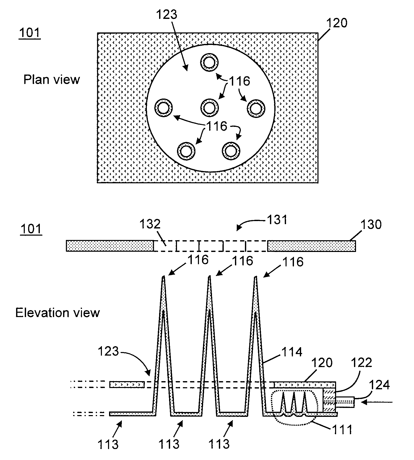
[0030]The present invention provides methods and apparatus for an improved ionization source for mass spectrometry. The following description is presented to enable one of ordinary skill in the art to make and use the invention and is provided in the context of a particular application and its requirements. It will be clear from this description that the invention is not limited to the illustrated examples but that the invention also includes a variety of modifications and embodiments thereto. Therefore the present description should be seen as illustrative and not limiting. While the invention is susceptible of various modifications and alternative constructions, it should be understood that there is no intention to limit the invention to the specific forms disclosed. On the contrary, the invention is to cover all modifications, alternative constructions, and equivalents falling within the essence and scope of the invention as defined in the claims. To more particularly describe th...


PUM

PropertyMeasurementUnit
widthaaaaaaaaaa
threshold velocityaaaaaaaaaa

Abstract

An electrospray ion source for a mass spectrometer includes an electrode comprising at least a first plurality of protrusions protruding from a base, each protrusion of the at least a first plurality of protrusions having a respective tip; a conduit for delivering an analyte-bearing liquid to the electrode; and a voltage source, wherein, in operation of the electrospray ion source, the analyte-bearing liquid is caused to move, in the presence of a gas or air, from the base to each protrusion tip along a respective protrusion exterior so as to form a respective stream of charged particles emitted towards an ion inlet aperture of the mass spectrometer under application of voltage applied to the electrode from the voltage source.

Description

FIELD OF THE INVENTION[0001]The present invention relates to ionization sources for mass spectrometry and, in particular, to a nano-electrospray ionization source comprising a surface having a plurality of protruding microscopic to sub-microscopic pillars, cones, needles, or wires each of which acts to emit ions from an analyte-bearing liquid applied to its exterior surface.BACKGROUND OF THE INVENTION[0002]The well-known technique of electrospray ionization is used in mass spectrometry to produce ions. In conventional electrospray ionization, a liquid is pushed through a very small charged capillary. This liquid contains the analyte to be studied dissolved in a large amount of solvent, which is usually more volatile than the analyte. The conventional electrospray process involves breaking the meniscus of a charged liquid formed at the end of the capillary tube into fine droplets using an electric field. The electric field induced between the electrode and the conducting liquid initi...

Claims


Application Information

Patent Timeline
Patent Type & Authority Patents(United States)
IPC IPC(8): H01J49/26H01J49/10H01J49/04H01B13/00
CPCH01J49/167Y10T29/49423Y10T29/49433H01J49/0018
Inventor MAKAROV, ALEXANDER A.WOUTERS, ELOY R.
Owner THERMO FINNIGAN
Why Eureka
Try Eureka