
Magnetic transfer device and magnetic transfer method

a magnetic transfer and magnetic field technology, applied in the field of magnetic transfer devices and magnetic transfer methods, can solve the problems of increasing write time, affecting the efficiency of hdd production, signal degradation, etc., and achieves the effects of reducing the diffusion of magnetic flux, avoiding uneven and effective application of the transfer magnetic field

Inactive Publication Date: 2012-06-26
FUJI ELECTRIC CO LTD
View PDF22 Cites 3 Cited by
  • Summary
  • Abstract
  • Description
  • Claims
  • Application Information

AI Technical Summary

Benefits of technology

The present invention provides a magnetic transfer device for transferring preformat information to a magnetic recording medium by applying a transfer magnetic field in a conjoined body comprising the master disk and the magnetic recording medium. The device includes a magnetic field generating structure with a pair of permanent magnets and a return yoke connected to the magnets. The device can effectively apply the transfer magnetic field to the conjoined body by moving the magnetic field generating structure in a radial direction with respect to the medium, starting from a position outside of the medium and moving radially inward and outward. The device can achieve uniform magnetic transfer without disturbing the transfer magnetic field in the process of separating the magnetic field generating structure from the conjoined body. The method of magnetic transfer using the device can ensure magnetic transfer through the whole magnetic recording medium. The device is lightweight and compact, and can be used in a small space.

Problems solved by technology

However, a recent increase in recording tracks has caused problems of increase in write time and degradation of efficiency in HDD production.
If the magnets are separated while stopping rotation, the magnetic field becomes non-uniform when the position of the magnets is separated, causing degradation of signals.
Further, the magnetic field required by magnetic transfer may result in an increase in the size of the magnetic transfer device for perpendicular magnetic recording media.
As a result, the transfer device needs to strengthen the rigidness of a part for holding the magnet, which leads to a large size of the transfer device.
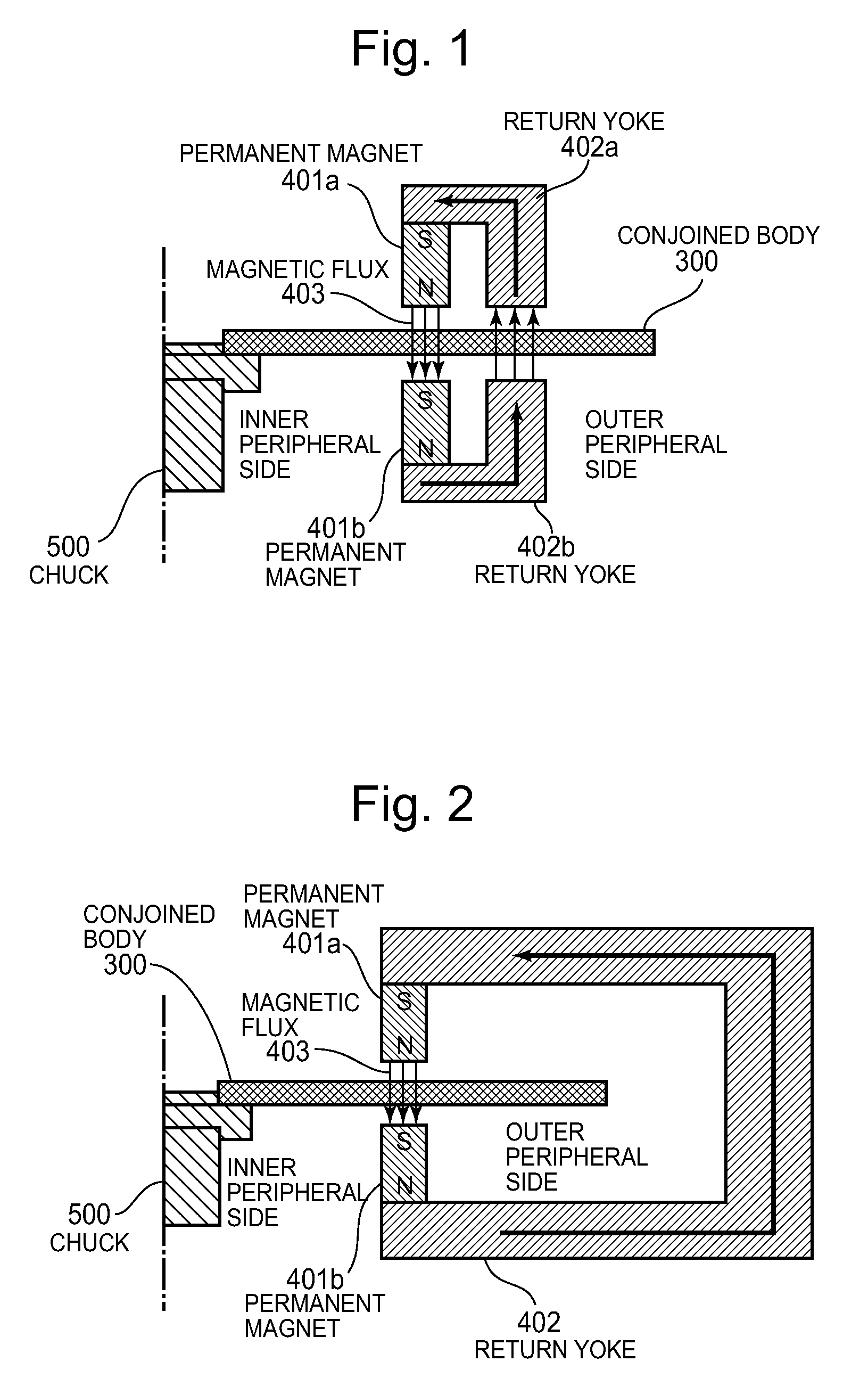
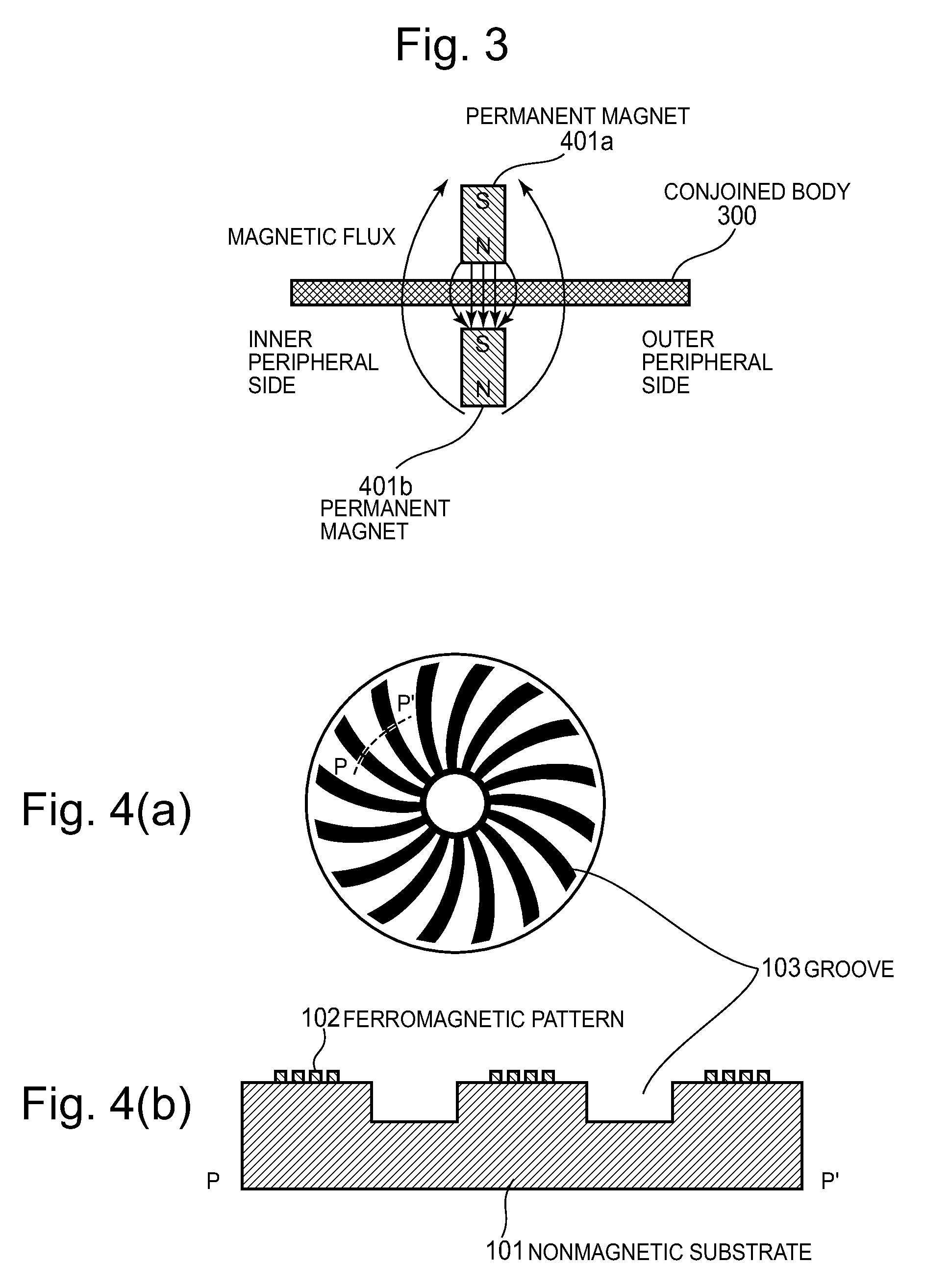
However, in the case where a transfer magnetic field is applied to a perpendicular magnetic recording medium by a pair of magnets, a pair of magnets simply having a reduced length still generates a diffused leakage flux as shown in FIG. 3, and a transfer magnetic field cannot be applied efficiently.

Method used


Image

  • Magnetic transfer device and magnetic transfer method
  • Magnetic transfer device and magnetic transfer method
  • Magnetic transfer device and magnetic transfer method

Examples


Embodiment Construction

[0037]Some preferred embodiments according to the present invention will be described in the following with reference to accompanying drawings. In the drawings, the same or equivalent parts are given the same symbol and repeated description is omitted.

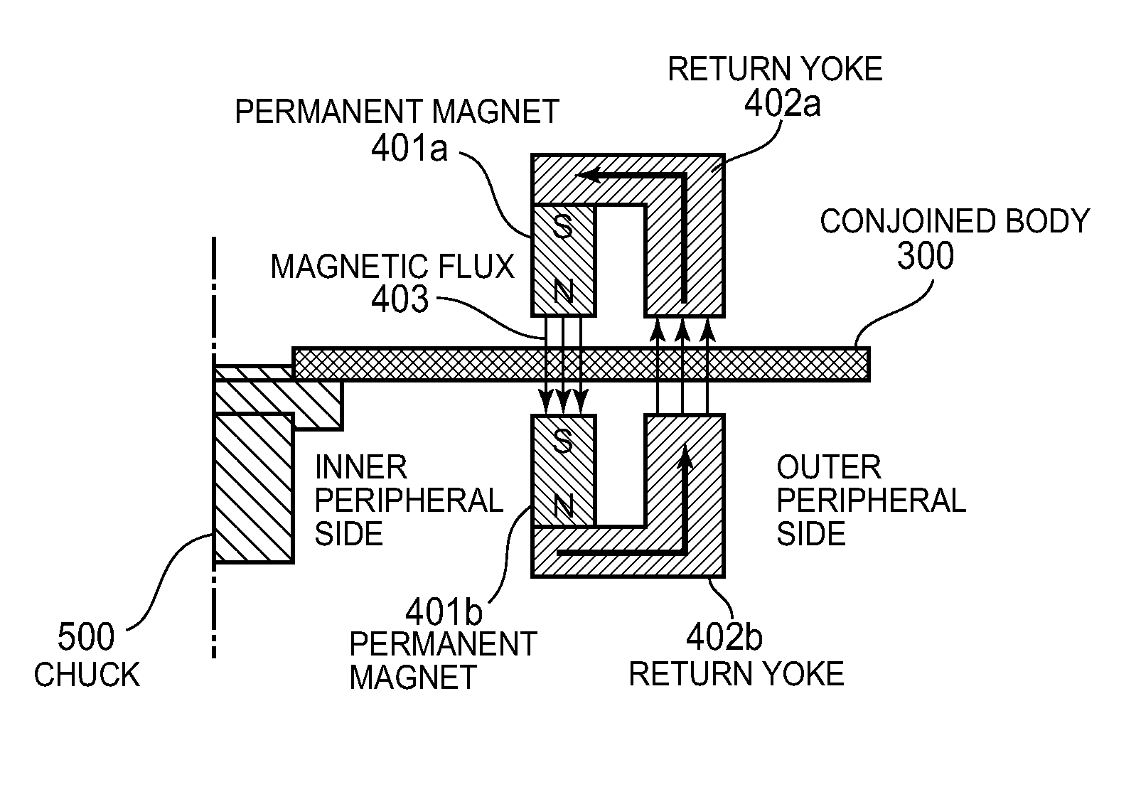
[0038]FIG. 1 is a schematic sectional view of a magnetic transfer device of an embodiment according to the present invention. In this embodiment, a magnetic field generating structure 400 (see FIG. 6), which applies a transferring magnetic field to a conjoined body composed of or including a master disk and a magnetic recording medium substantially perpendicular to the transferring magnetic field, comprises a pair of permanent magnets 401a and 401b and a pair of return yokes 402a and 402b. Each permanent magnet includes a first type of magnetic pole and a second type of magnetic pole having a different polarity from one another. The first type of magnetic pole of the permanent magnet 401a opposes the second type of magnetic pole of the...


PUM

PropertyMeasurementUnit
flying heightaaaaaaaaaa
depthaaaaaaaaaa
magnetic fieldaaaaaaaaaa

Abstract

A magnetic transfer device and method are provided. A magnetic field generating structure comprises a pair of permanent magnets connected to a return yoke. Respective magnetic poles of the magnets, of a different polarity from one another, oppose each other with a conjoined body disposed therebetween. The magnetic field generating structure is moved from a position at an outer periphery of the conjoined body, to a position at an inner periphery of the conjoined body, and then moved from the position at the inner periphery across the conjoined body toward the outer periphery, to a position outside of the conjoined body. The return yoke is positioned at a radially more outward position, toward the outer periphery, than are the permanent magnets. The movement of the magnetic field generating structure is carried out while maintaining a constant distance from the rotating conjoined body.

Description

CROSS-REFERENCE TO RELATED APPLICATION[0001]This application claims priority under 35 U.S.C. §119 from Japanese Patent Application 2009-166785, filed Jul. 15, 2009, the entirety of which is incorporated herein by reference.BACKGROUND OF THE INVENTION[0002]1. Field of the Invention[0003]The present invention relates to a magnetic transfer device and a magnetic transfer method for transferring preformat information to a magnetic recording layer of a perpendicular magnetic recording medium, the magnetic transfer being carried out by making close contact between a surface of transfer information pattern of a master disk that has a transfer information pattern of ferromagnetic material corresponding to the preformat information to be transferred, and a recording surface of the perpendicular magnetic recording medium that has a magnetic recording layer, and by applying a transferring magnetic field in a direction perpendicular to the surface of close contact.[0004]2. Description of the Re...

Claims


Application Information

Patent Timeline
Patent Type & Authority Patents(United States)
IPC IPC(8): G11B5/86
CPCB82Y10/00G11B5/743G11B5/855G11B5/865
Inventor KIKUCHI, HIROTO
Owner FUJI ELECTRIC CO LTD
Learn More