
Enhanced stability implantable medical device

a medical device and stability technology, applied in the field of medical devices, can solve the problems of medical device failure, adverse effects on the function of devices, fracture of output devices, etc., and achieve the effects of stabilizing the medical device once implanted, small cross-section, and maintaining high stability once implanted

Inactive Publication Date: 2012-06-26
STEALTH THERAPEUTICS
View PDF106 Cites 34 Cited by
  • Summary
  • Abstract
  • Description
  • Claims
  • Application Information

AI Technical Summary

Benefits of technology

"The present invention provides a medical device that can be implanted through a small incision and maintain stability within the body of a patient. The device can be morphed between a smaller profile and a larger profile after being implanted. The device can also be stabilized after implantation with a simple and reliable process. The invention also includes a method for implanting and stabilizing the device. The technical effects of the invention include reduced size incisions, high stability, and ease of implantation and stabilization."

Problems solved by technology

“Twiddlers Syndrome” refers to a situation where a subcutaneous medical device has been manipulated by the patient (or sometimes spontaneously) and flipped over upon itself one or more times, so that the device function is adversely affected.
This can lead to fracture of output devices and potential failure of the medical device.
As the size of the incision increases, the difficulty associated with hiding the incision from visual detection by others is increased.
With known prior art technology of the shape described above, such incisions have not been minimized.
However, such miniaturization has limits and other complications are associated with such miniaturization including enhanced cost and potentially reduced battery life, reduced storage capacity for medical preparations to be delivered and other potentially adverse effects.

Method used


Image

  • Enhanced stability implantable medical device
  • Enhanced stability implantable medical device
  • Enhanced stability implantable medical device

Examples


Embodiment Construction

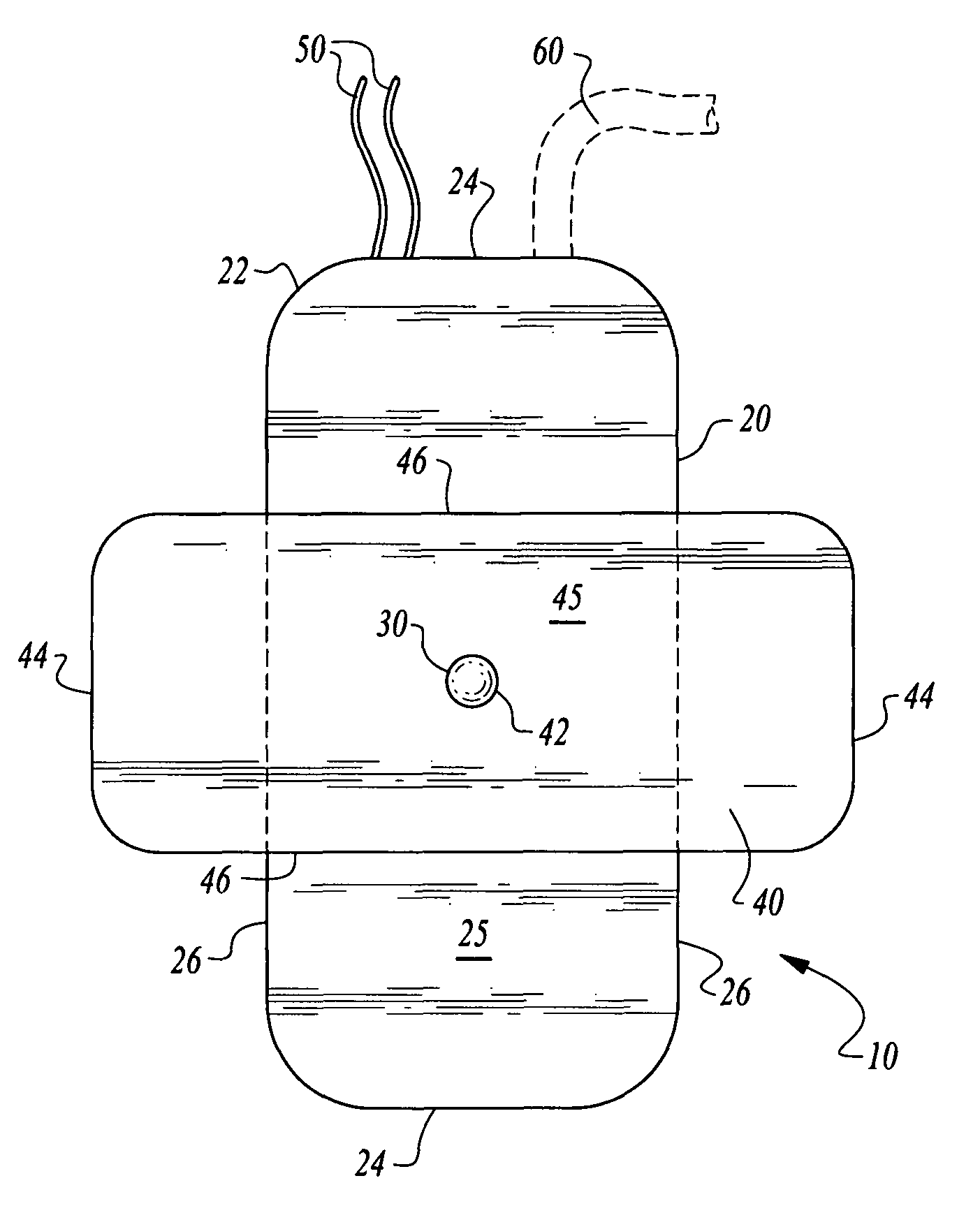
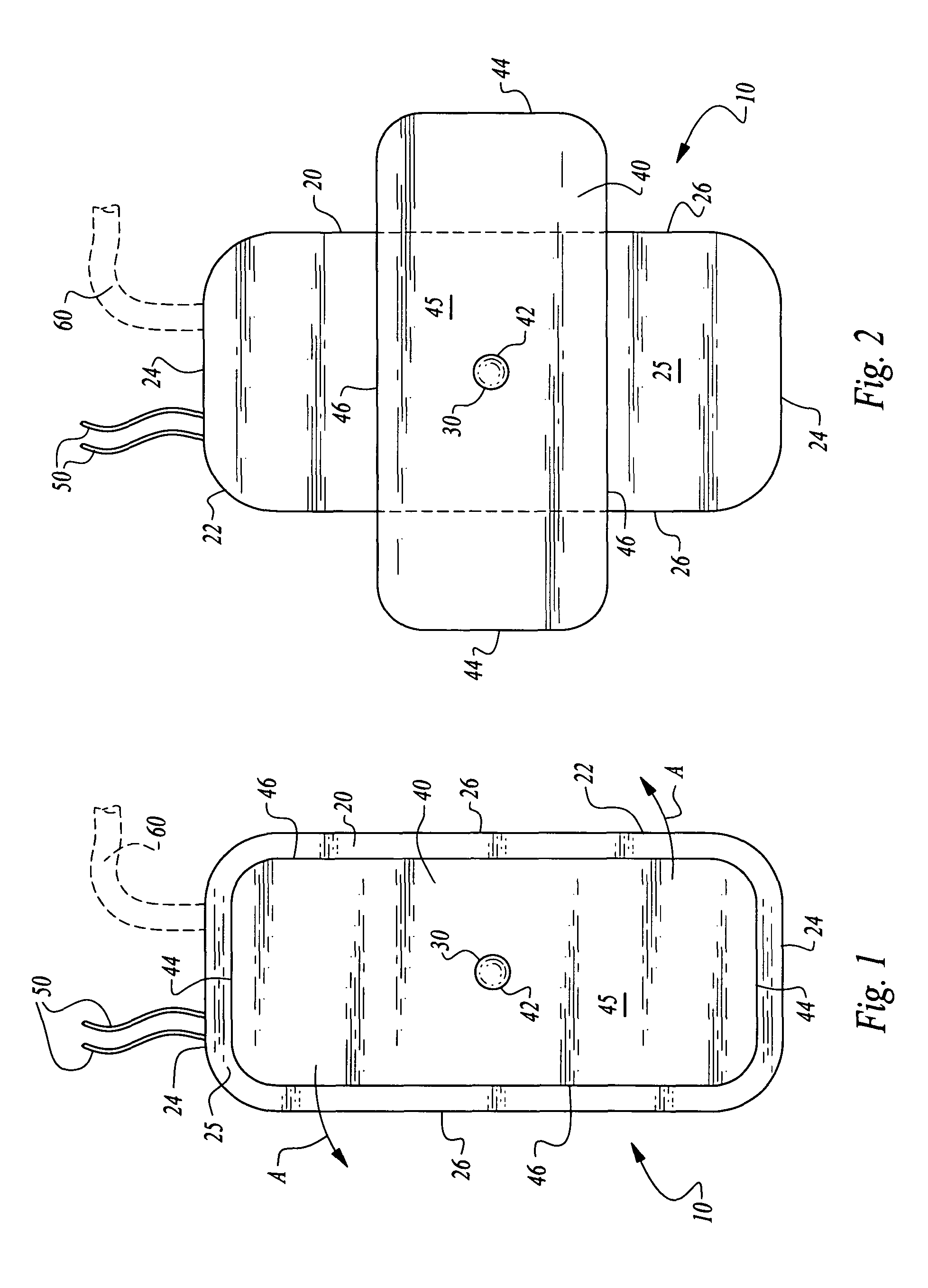
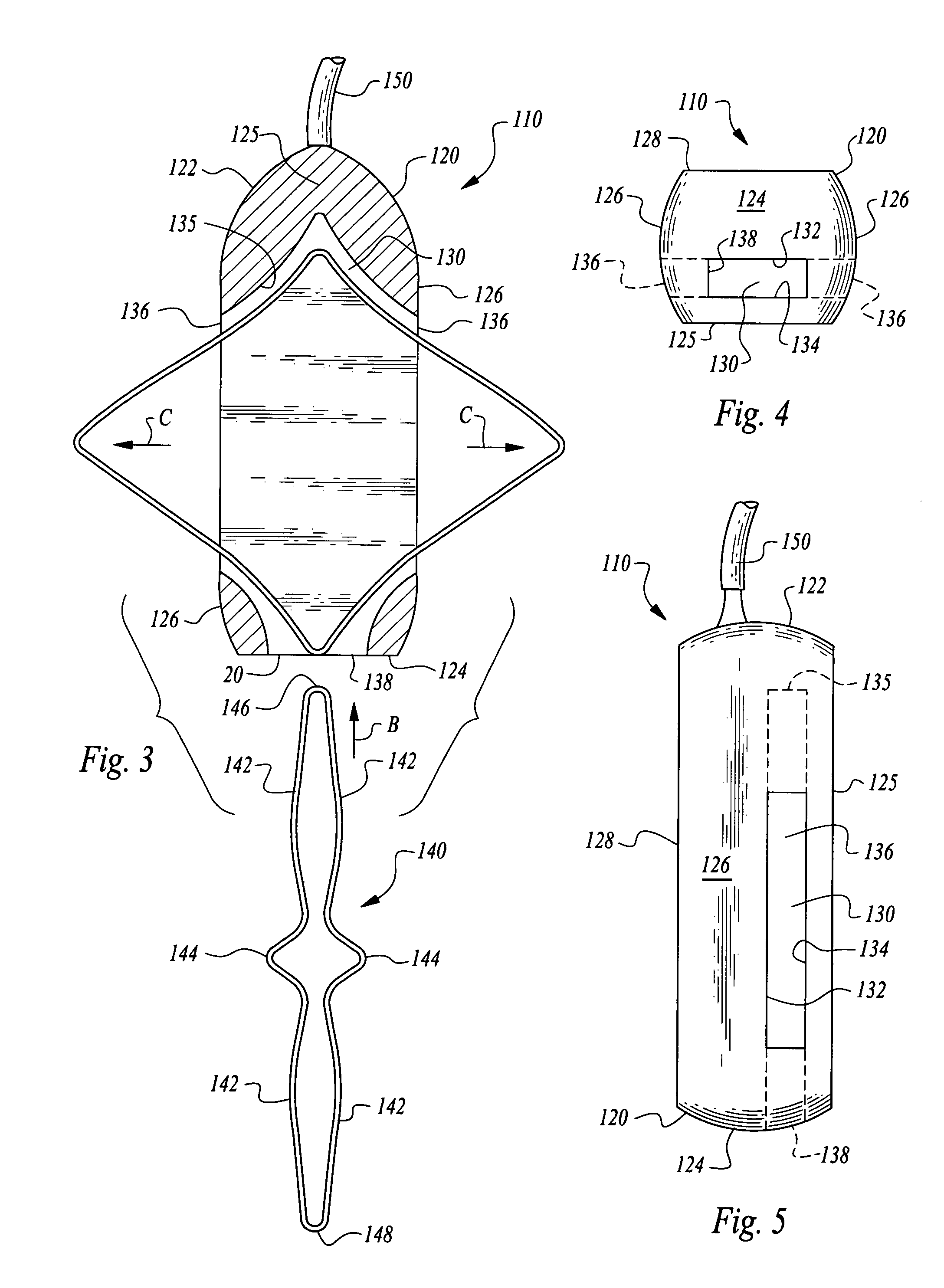
[0028]Referring to the drawings, wherein like reference numerals represent like parts throughout the various drawing figures, reference numeral 10 (FIGS. 1 and 2) is directed to a pacemaker as one form of medical device illustrative of the enhanced stability implantable medical device of this invention. In addition to pacemakers 10, infusion pumps, ports and other medical devices could similarly be provided and utilize the same stabilization element and housing 20 as the pacemaker 10. The pacemaker 10 has an elongate form to allow it to be implanted through a small incision. A shape of the housing 20 of the pacemaker 10 is modified after arriving at the subcutaneous implantation site to enhance stability of the pacemaker 10 or other medical device implant. Two alternative embodiments are also disclosed herein including a first alternative pacemaker 110 (FIGS. 3-7) and a second alternative pacemaker 210 (FIGS. 8 and 9).

[0029]In essence, and with particular reference to FIGS. 1 and 2,...


PUM


Abstract

An implantable medical device is provided which has a housing of an elongate form to minimize a size of an incision required for implantation. A stabilizing element is associated with the elongated form housing for the medical device. The stabilizing element transitions from a low profile initial form to a higher width final form to provide the medical device with a stabilized footprint after implantation. The stabilizing element is in the form of a rotating wing in one embodiment. In another embodiment, the stabilizing element is in the form of an expanding loop that can bend to extend out of side openings of a cavity within the housing, to provide such stabilization at the implantation site. The medical device can be in the form of a pacemaker, infusion pump, vascular access port or other subcutaneously implanted medical device.

Description

CROSS-REFERENCE TO RELATED APPLICATIONS[0001]This application claims benefit under Title 35, United States Code §119(e) of U.S. Provisional Application No. 60 / 960,640 filed on Oct. 9, 2007.[0002]This application incorporates by reference the contents of U.S. Pat. No. 7,708,722, in its entirety.FIELD OF THE INVENTION[0003]The following invention relates to medical devices which are implanted subcutaneously to provide a therapeutic benefit for a patient at the implantation site. More particularly, this invention relates to subcutaneously implanted medical devices which have a low profile form for minimally invasive implantation through a small incision, but which can be adjusted in form to have a highly stable configuration after implantation to resist movement after implantation. Such medical devices could be in the form of pacemakers, infusion devices, such as infusion pumps, vascular access ports, or other medical devices which are taught in the prior art to be implanted subcutaneo...

Claims


Application Information

Patent Timeline
Patent Type & Authority Patents(United States)
IPC IPC(8): A61N1/378
CPCA61M5/14276A61N1/375A61M25/04A61M2039/0223A61N1/37512A61N1/37518
Inventor GLENN, BRADLEY J.
Owner STEALTH THERAPEUTICS
Learn More