Suspension device and method for use with a vehicle

a suspension device and vehicle technology, applied in the direction of shock absorbers, instruments, cycle equipment, etc., can solve the problems of reducing the angle of rotation about the roll centre of the vehicle, and achieve the effect of improving the running characteristics of the vehicl

Active Publication Date: 2012-06-26
BAE SYSTEMS HAGGLUNDS AKTIEBOLAG
View PDF21 Cites 21 Cited by
  • Summary
  • Abstract
  • Description
  • Claims
  • Application Information

AI Technical Summary

Benefits of technology

[0010]An object of the present invention is to provide a spring device for a vehicle which improves the running characteristics of the vehicle by, for example, cornering, braking and accelerating without impairing comfort and traversability.
[0011]An additional object of the present invention is to provide a method for providing a spring / damping action of a vehicle, which improves the running characteristics of the vehicle by, for example, cornering, braking and accelerating without impairing comfort and traversability.

Problems solved by technology

The angle of rotation about the roll centre of the vehicle is reduced due to lowered centre of gravity and due to the fact that out-configuration of, for example, the inner spring leg during cornering does not assist in rotating the vehicle since it is locked or substantially locked.

Method used


Image

  • Suspension device and method for use with a vehicle
  • Suspension device and method for use with a vehicle
  • Suspension device and method for use with a vehicle

Examples


first embodiment

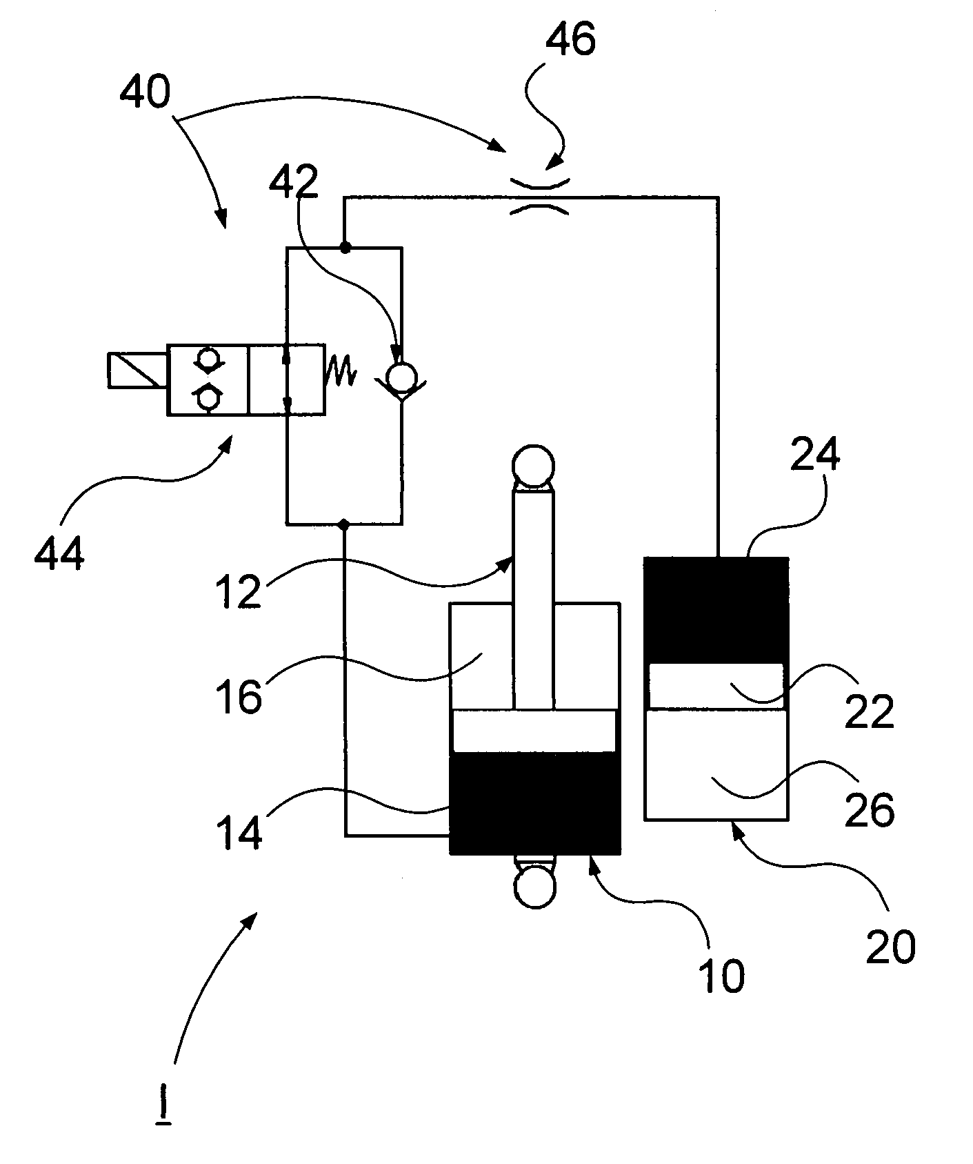
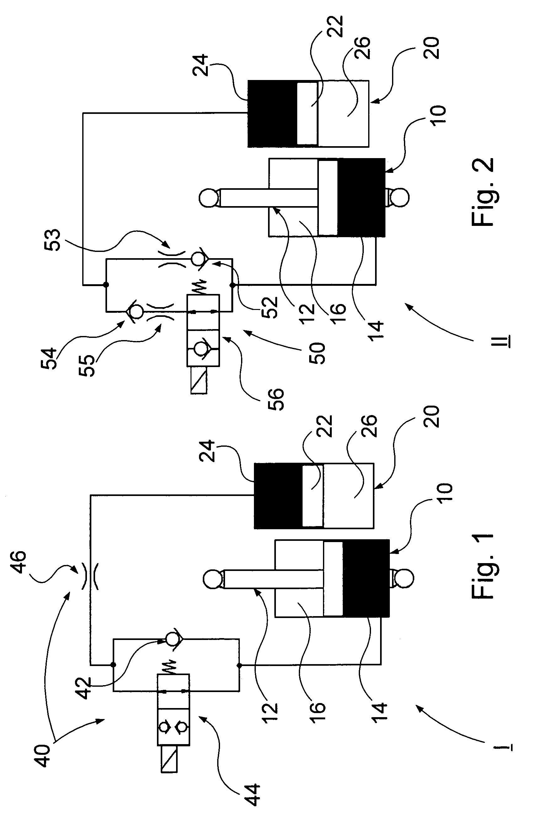
[0036]FIG. 1 schematically shows a suspension device I according to the present invention. The suspension device I comprises in- and out-configurations, respectively. The suspension device I comprises a first space 10 and a second space 20 separated by means of a valve configuration 40, which is in fluid communication with the first and the second spaces, the valve configuration 40 being arranged to control the flow of the fluid between the first and second spaces.

[0037]The suspension device I further comprises a piston stem 12 glidably arranged in the first space. The piston stem 12 is intended to be connected to a wheel of the vehicle via a linkage. The piston stem 12 is arranged in the first space 10 in such a way that it is divided into a first cavity 14 and a second cavity 16, the first cavity 14 being in fluid communication with the valve configuration 40 and containing a first fluid, preferably oil, and the second cavity containing a second fluid in the form of a gaseous medi...

second embodiment

[0045]The valve configuration 50 comprises a first pair of valves 52, 53, a second pair of valves 54, 55 and a controllable valve member 56. The first pair of valves is arranged parallel to the second pair of valves. The first pair of valves comprises a first non-return valve 52 and a first throttle valve 53 arranged in series. The second pair of valves comprises a second non-return valve 54 and a second throttle valve 55 arranged in series. The controllable valve member 56 is arranged in series with the second valve member 54, 55.

[0046]The first non-return valve 52 is arranged to allow oil through from the first cavity 14 during compression, i.e. during movement of the piston stem in the direction of compression, i.e. during retraction of the piston stem 12. The first non-return valve 52 is further arranged not to allow oil through the third cavity 24 during expansion, i.e. during movement of the piston in the direction of expansion, i.e. during extension of the piston stem 12.

[00...

third embodiment

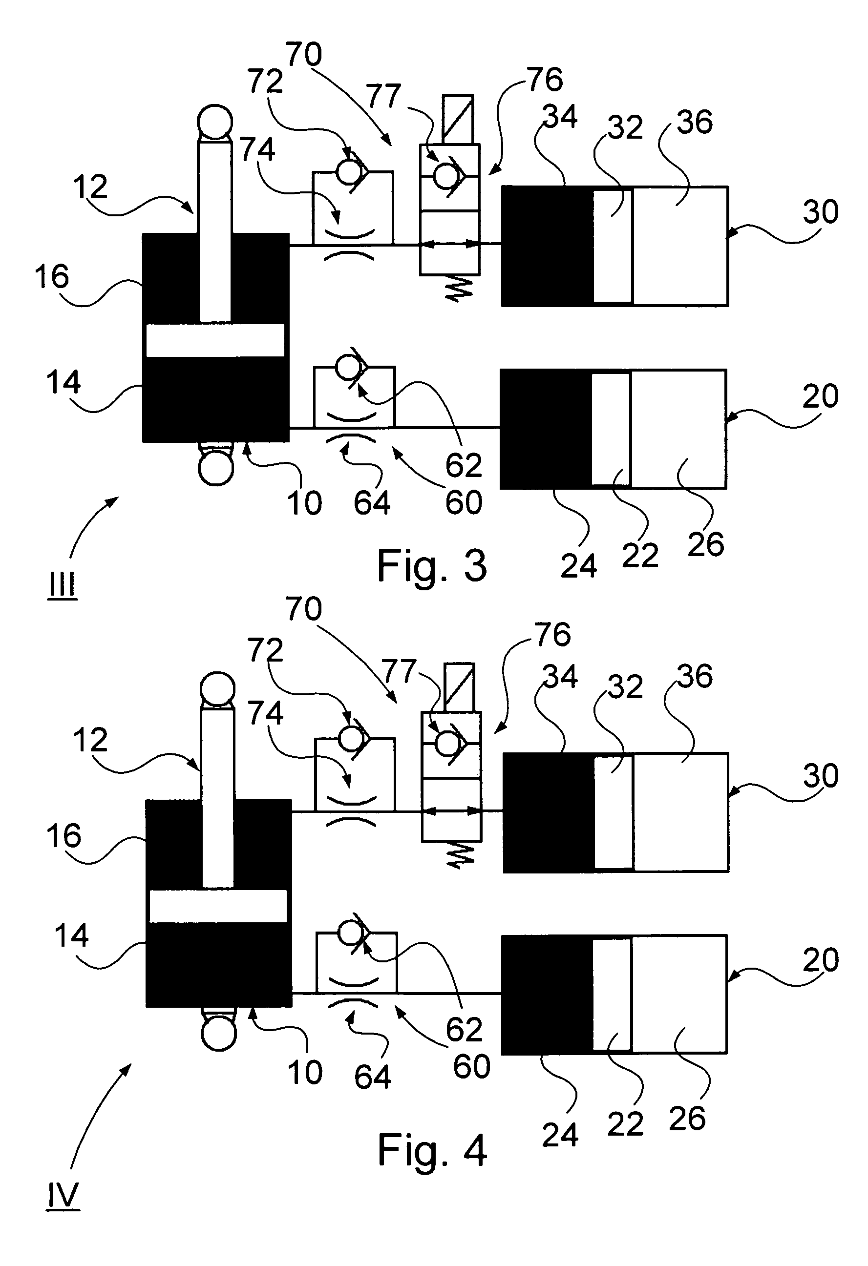
[0051]FIG. 3 schematically shows a suspension device III according to the present invention. The suspension device III comprises in- and out-configurations, respectively. The suspension device III for a vehicle comprises a first space 10, a second space 20 and a third space 30. The first space 10 and the second space 20 are separated by means of a first valve configuration 60, which is in fluid communication with the first space 10 and second space 20, the first valve configuration 60 being arranged to control the fluid between the first space 10 and second space 20. The first space 10 and the third space 30 are separated by means of a second valve configuration 70, which is in fluid communication with the first space 10 and third space 30, the second valve configuration 70 being arranged to control the fluid between the first space 10 and the third space 30.

[0052]The suspension device III further comprises a piston stem 12 glidably arranged in the first space 10. The piston stem 12...


PUM


Abstract

A suspension device has in- and out-configurations for use with a vehicle, including means for damping and / or spring action, the damping and / or spring action being controllable, wherein the controllability of the damping and / or spring action includes a locked or substantially locked state in the out-configuration. A method of using the suspension device with a vehicle is also provided.

Description

CROSS-REFERENCE TO RELATED APPLICATIONS[0001]This application claims the benefit of the filing date of Swedish Patent Application No. 0702481-3 filed Nov. 9, 2007, the disclosure of which is hereby incorporated herein by reference.BACKGROUND OF THE INVENTION[0002]The present invention relates to a suspension device comprising in- and an out-configurations, respectively, for a vehicle. The present invention also relates to a method for providing a damping and / or springing action with in- and out-configurations of a vehicle. The present invention further relates to a vehicle. The present invention also relates to a computer programme and a computer programme product for performing the method.[0003]Road holding, running characteristics and comfort are important parameters of vehicles such as cars, military vehicles, trucks and the like. In order to improve road holding, running characteristics and comfort, vehicles are equipped with suspensions systems, which is arranged to protect the...

Claims


Application Information

Patent Timeline
Patent Type & Authority Patents(United States)
IPC IPC(8): B60G17/018
CPCB60G13/14F16F9/56B60G17/0152B60G17/0162B60G17/08B60G17/005B60G2202/154B60G2202/24B60G2204/4605B60G2204/62B60G2206/41B60G2300/07B60G2400/0511B60G2400/104B60G2400/204B60G2400/41B60G2400/63B60G2400/821B60G2500/10B60G2500/11B60G2500/2062B60G2600/18B60G2600/184B60G2600/70B60G2800/012B60G2800/24B60G17/01908B60G17/0523B60G17/0525
Inventor HAGGLUND, HENRIKCHRISTENSEN, ASSAR
Owner BAE SYSTEMS HAGGLUNDS AKTIEBOLAG
Why Eureka
Try Eureka