Supercharge Your Innovation With Domain-Expert AI Agents!

Error-correcting apparatus including multiple error-correcting modules functioning in parallel and related method

a technology of error correction and error correction module, applied in the field of error correction coding, can solve the problems of severe fading or interference, output of a communication channel to be different from its input, and cannot compensate completely

Active Publication Date: 2012-06-26
COMM ADVANCES LLC
View PDF26 Cites 2 Cited by
  • Summary
  • Abstract
  • Description
  • Claims
  • Application Information

AI Technical Summary

Benefits of technology

This approach significantly improves error correction performance by allowing correction of up to twice the errors in burst noise conditions, reducing error propagation and enhancing reliability in communication systems.

Problems solved by technology

Various types of noise, distortion, and interference are commonly seen factors that deteriorate signal communication quality and cause the output of a communication channel to be different from its input.
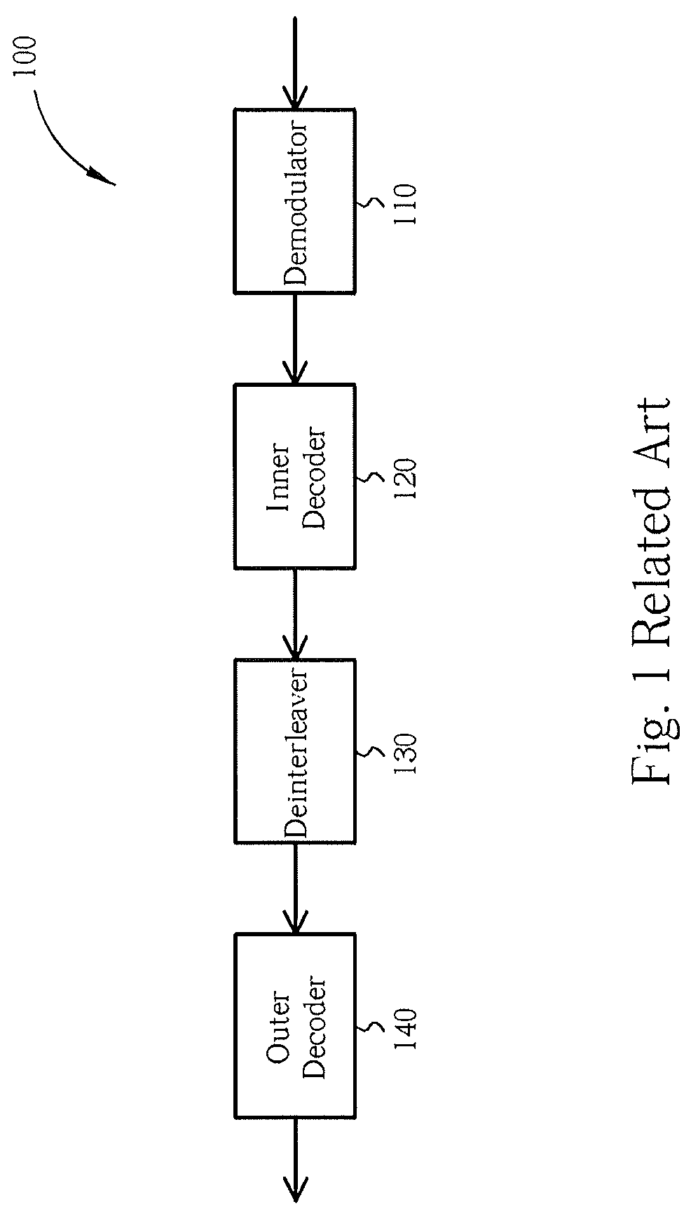
However, in some communication systems, especially in terrestrial broadcasting systems, complex multi-path channels would induce severe fading or interference that the equalizer of the demodulator 110 cannot compensate entirely.
In such circumstances, burst noise may causes errors of the inner decoder 120 to propagate to the outer decoder 140 and even the deinterleaver 130 cannot scatter them efficiently.
The outer decoder 140 with only t-error correction capability may not be sufficient.
However, for receiver-ends, sometimes it is not easy to mark erasure locations exactly and efficiently.
For example, a few distorted symbols occurring at the output end of the demodulator 110 may be corrected by Viterbi algorithm at the moment, but may cause error propagation for decoding some clear symbols later.
In this situation, the uncertainty of an exact erasure marking procedure increases in severe burst noise and in low signal-to-noise ratio (SNR) situations.
Then, an erroneous location marking for erasure will deteriorate the error correction capability of error-erasure decoder.

Method used


Image

  • Error-correcting apparatus including multiple error-correcting modules functioning in parallel and related method
  • Error-correcting apparatus including multiple error-correcting modules functioning in parallel and related method
  • Error-correcting apparatus including multiple error-correcting modules functioning in parallel and related method

Examples


Embodiment Construction

[0015]In the following descriptions, (n, k, 2t) RS codes will be used as an example for illustrating the ideas of the present invention. To avoid codewords with t errors or less than t errors from being mistakenly decoded on account of erroneous erasure marking procedures, and to enhance error-correcting performance for codewords with more than t errors, the following embodiment includes both an error decoder and an error-erasure decoder functioning in parallel to decoded an RS encoded signal.

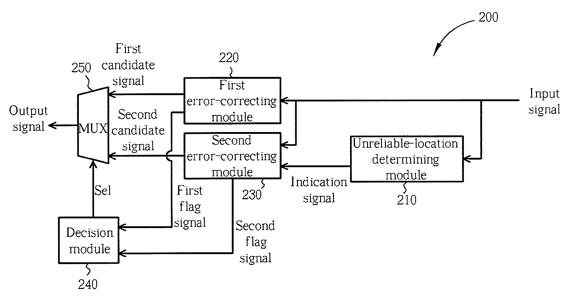
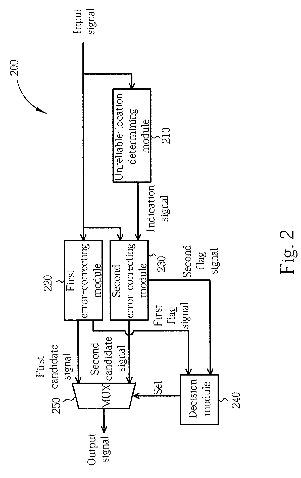
[0016]FIG. 2 shows a block diagram of an apparatus for error-correcting an input signal to generate an output signal according to an embodiment of the present invention. The input signal is an (n, k, 2t) RS encoded signal. The apparatus 200 of this embodiment includes an unreliable-location determining module 210, a first error-correcting module 220, a second error-correcting module 230, a decision module 240, and a multiplexer 250. The unreliable-location determining module 210 determines unre...


PUM


Abstract

An apparatus for error-correcting an input signal to generate an output signal. The apparatus includes an unreliable-location determining module for determining unreliable-locations of the input signal and generating an indication signal accordingly, a first error-correcting module for error-correcting the input signal to generate a first candidate signal, a second error-correcting module coupled to the unreliable-location determining module for error-correcting the input signal with reference to the indication signal to generate a second candidate signal, and a selecting module coupled to the first and second error-correcting modules for selecting one of the first and second candidate signals to be the output signal.

Description

CROSS REFERENCE TO RELATED APPLICATION[0001]This application is a continuation application for U.S. patent application Ser. No. 11 / 160,927 filed Jul. 15, 2005 (now issued as U.S. Pat. No. 7,673,222).BACKGROUND[0002]The present invention relates to error-correcting coding, and more particularly, to an error-correcting apparatus including multiple error-correcting modules functioning in parallel and a related method.[0003]Various types of noise, distortion, and interference are commonly seen factors that deteriorate signal communication quality and cause the output of a communication channel to be different from its input. Error-correcting coding is a technique that can be adopted in digital communication systems to help transceivers resist the above-mentioned factors, reduce the probability of errors, and enhance the reliability of the outputted data.[0004]Concatenated coding is a kind of error-correcting coding technique that implements multiple levels of coding. Generally speaking,...

Claims


Application Information

Patent Timeline
Patent Type & Authority Patents(United States)
IPC IPC(8): H03M13/00
CPCH03M13/3707H03M13/45H03M13/1515H03M13/373
Inventor CHIOU, RONG-LIANG
Owner COMM ADVANCES LLC
Features
  • R&D
  • Intellectual Property
  • Life Sciences
  • Materials
  • Tech Scout
  • Unparalleled Data Quality
  • Higher Quality Content
  • 60% Fewer Hallucinations
Learn More