Extensible verification system

a verification system and extension technology, applied in the field of extension verification system, can solve the problems of single out-of-the-box computer aided design (cad) verification solution (or application) not being able to accurately validate all design requirements for today's complex designs, and the solution provider has not been able to support all these requirements

Active Publication Date: 2012-06-26
CADENCE DESIGN SYST INC
View PDF28 Cites 0 Cited by
  • Summary
  • Abstract
  • Description
  • Claims
  • Application Information

AI Technical Summary

Problems solved by technology

As electronic design complexity increases in many design domains including signal integrity (SI), electromagnetic interference (EMI), manufacturing, and power, the number and type of constraints imposed on a design has grown substantially.
It is now clear that a single out-of-the-box computer aided design (CAD) verification solution (or application) is not sufficient to accurately validate all design requirements for today's complex designs.
Solution providers have not been able to support all these requirements due to the diverse range of customer needs and narrow applicability of each.
The overall solution is not well integrated to the original application so its usefulness is limited and not very modular, so reuse is difficult.
Even if the verification system meets these two criteria, it may still not be delivered for a significant time due to resource or scheduling issues.
This delay may not be acceptable in today's consumer driven marketplace.
Other factors effecting today's systems create difficulties for users requiring custom extensions.
Systems do not do a good job keeping measurements simple and coding them using a proven set of lower-level functions or predicates.
In certain situations, the report may be too late and can result in significant design re-work.
In situations where batch verification is necessary and acceptable, the reports generated by today's systems can be disjoint, not providing an adequate level of integration.

Method used


Image

  • Extensible verification system
  • Extensible verification system
  • Extensible verification system

Examples


Embodiment Construction

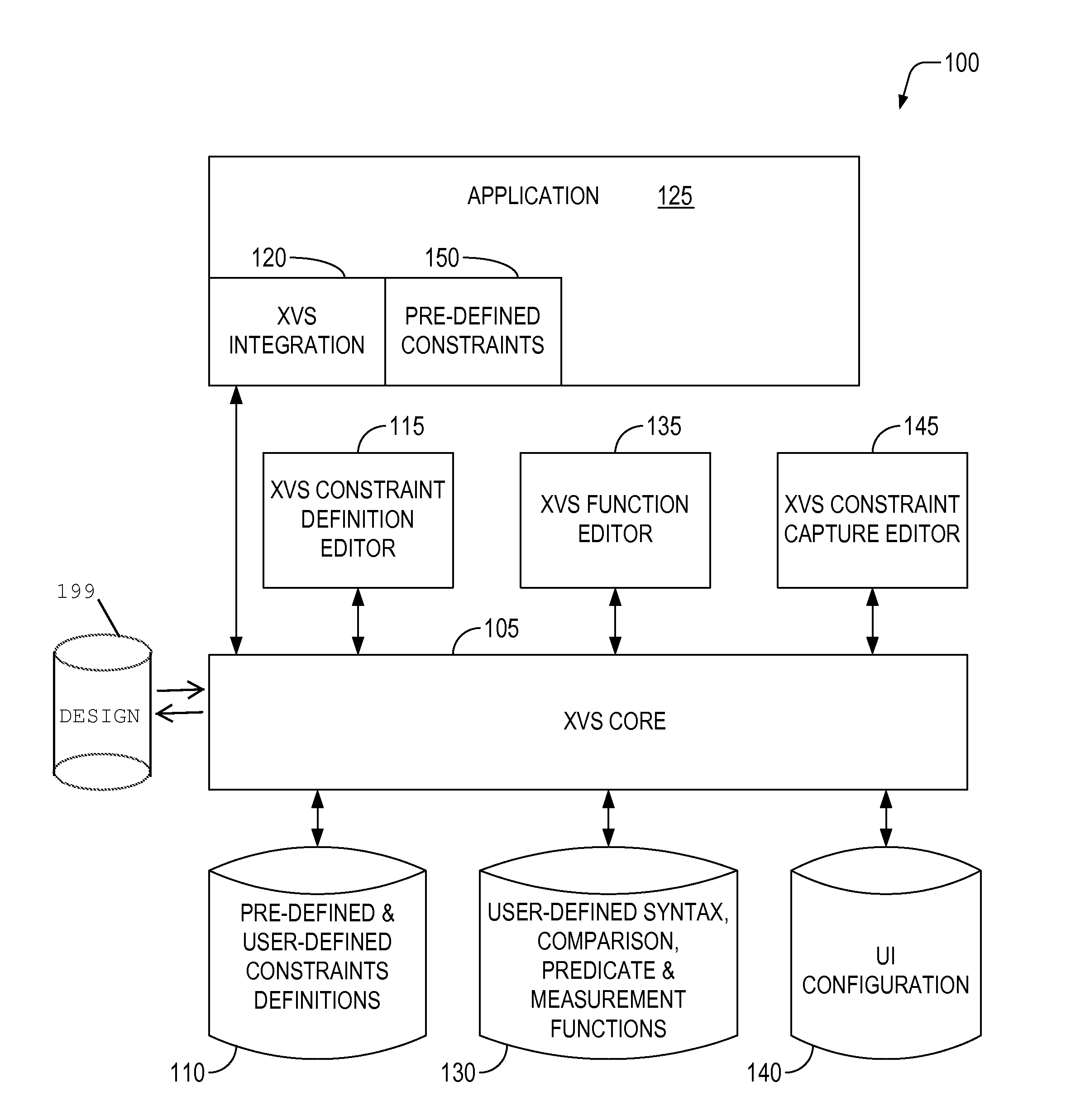
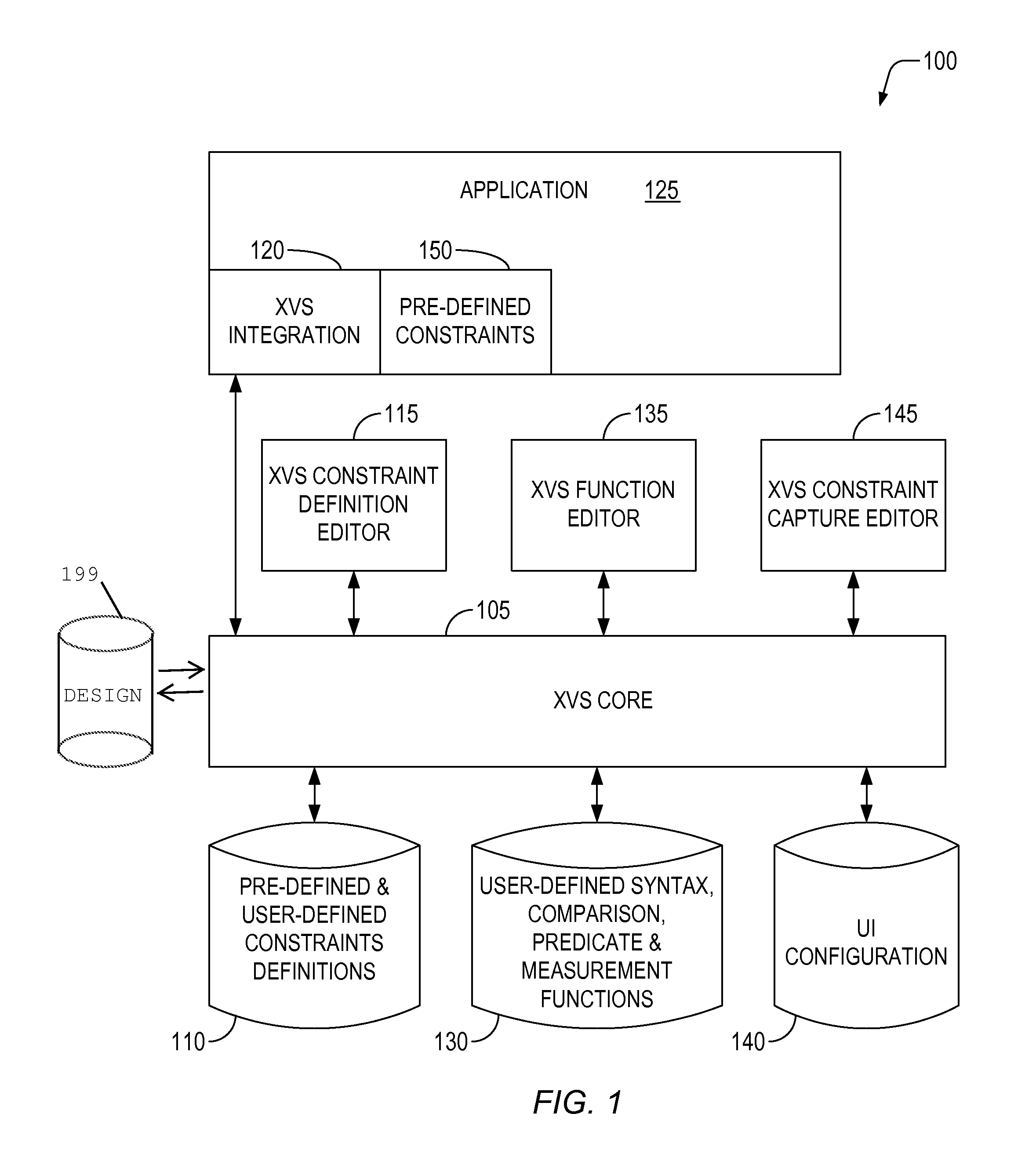
[0012]Reference now will be made in detail to embodiments of the disclosed invention, one or more examples of which are illustrated in the accompanying drawings. Each example is provided by way of explanation of the present technology, not limitation of the present technology. In fact, it will be apparent to those skilled in the art that modifications and variations can be made in the present technology without departing from the spirit and scope thereof. For instance, features illustrated or described as part of one embodiment may be used on another embodiment to yield a still further embodiment. Thus, it is intended that the present subject matter covers such modifications and variations as come within the scope of the appended claims and their equivalents.

[0013]The present invention includes an eXtensible Verification System (XVS) which can be configured to validate a product across all unique design challenges based upon any specific set of requirements or constraints. User-defi...


PUM


Abstract

An extensible design verification system and methods thereof are disclosed. Pre-defined constraints from an integrated verification application are registered with a core which manages the verification system. The core is utilized by the integrated verification application to execute one or more verification tasks to generate a result. The result can be captured by a user interface. Constraints and the user-interface can be either pre-defined or user-defined. User-defined constraints and interface are managed in the same manner as those that are pre-defined. The user-defined constraints and interface are exportable for reuse by other designs.

Description

BACKGROUND OF THE INVENTION[0001]As electronic design complexity increases in many design domains including signal integrity (SI), electromagnetic interference (EMI), manufacturing, and power, the number and type of constraints imposed on a design has grown substantially. It is now clear that a single out-of-the-box computer aided design (CAD) verification solution (or application) is not sufficient to accurately validate all design requirements for today's complex designs. Most companies have unique requirements based upon their design practices and products they are trying to deliver. Solution providers have not been able to support all these requirements due to the diverse range of customer needs and narrow applicability of each. Users have had to add extensions to their applications to cover their new design constraints. Adding user-defined extensions to verification testing has required users to either create a standalone verification test, or request the solutions provider to ...

Claims


Application Information

Patent Timeline
Patent Type & Authority Patents(United States)
IPC IPC(8): G06F17/50
CPCG06F17/5009G06F2217/06G06F2111/04G06F30/20
Inventor ROESLER, ROBERT
Owner CADENCE DESIGN SYST INC
Why Eureka
Try Eureka