
Wireless speaker system for use with ceiling fans

a speaker system and ceiling fan technology, applied in the field of ceiling fan wireless speaker system, can solve the problems of poor sound quality, poor sound distribution, and difficulty in installation

Active Publication Date: 2012-07-10
CB LLC
View PDF16 Cites 36 Cited by
  • Summary
  • Abstract
  • Description
  • Claims
  • Application Information

AI Technical Summary

Benefits of technology

The solution provides centralized audio entertainment, space-saving design, improved sound distribution, reduced heat interference, and simplified installation, while eliminating the need for separate speaker stands or tables and additional wiring.

Problems solved by technology

Additional problems in the prior art, particularly in the combination of speakers with other items, include poor sound quality, poor sound distribution, overheating, difficulty in installation, incompatibility between the speaker and the item, and other problems known by those of ordinary skill in the art.

Method used


Image

  • Wireless speaker system for use with ceiling fans
  • Wireless speaker system for use with ceiling fans
  • Wireless speaker system for use with ceiling fans

Examples


first embodiment

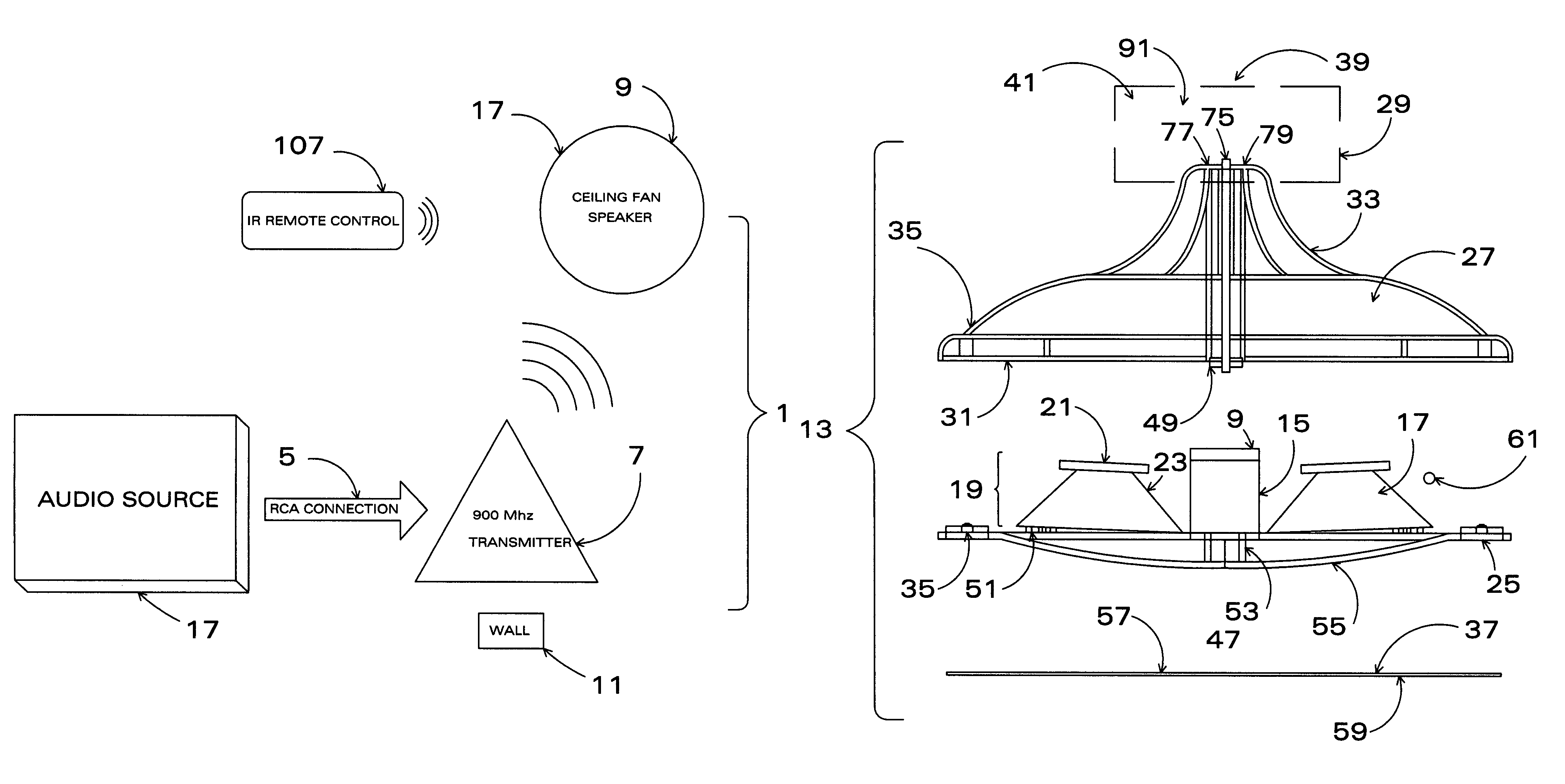
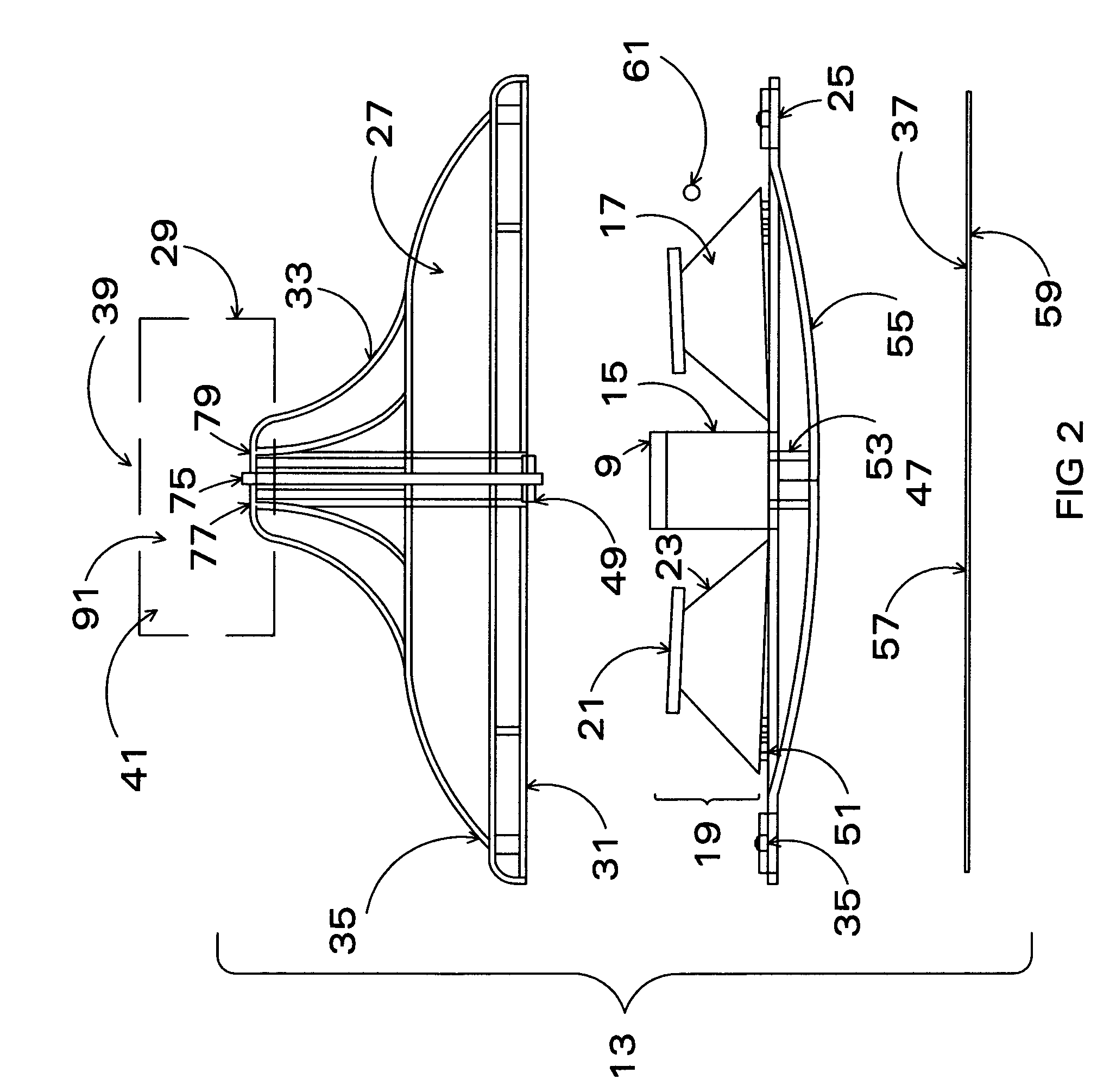
[0028]an element of the present invention is detailed in FIGS. 2, 3, 4A, 4B and 4C, wherein the speaker 17 or speakers 17 of the present invention are directed downward from the ceiling, and away from the existing fan assembly 29.

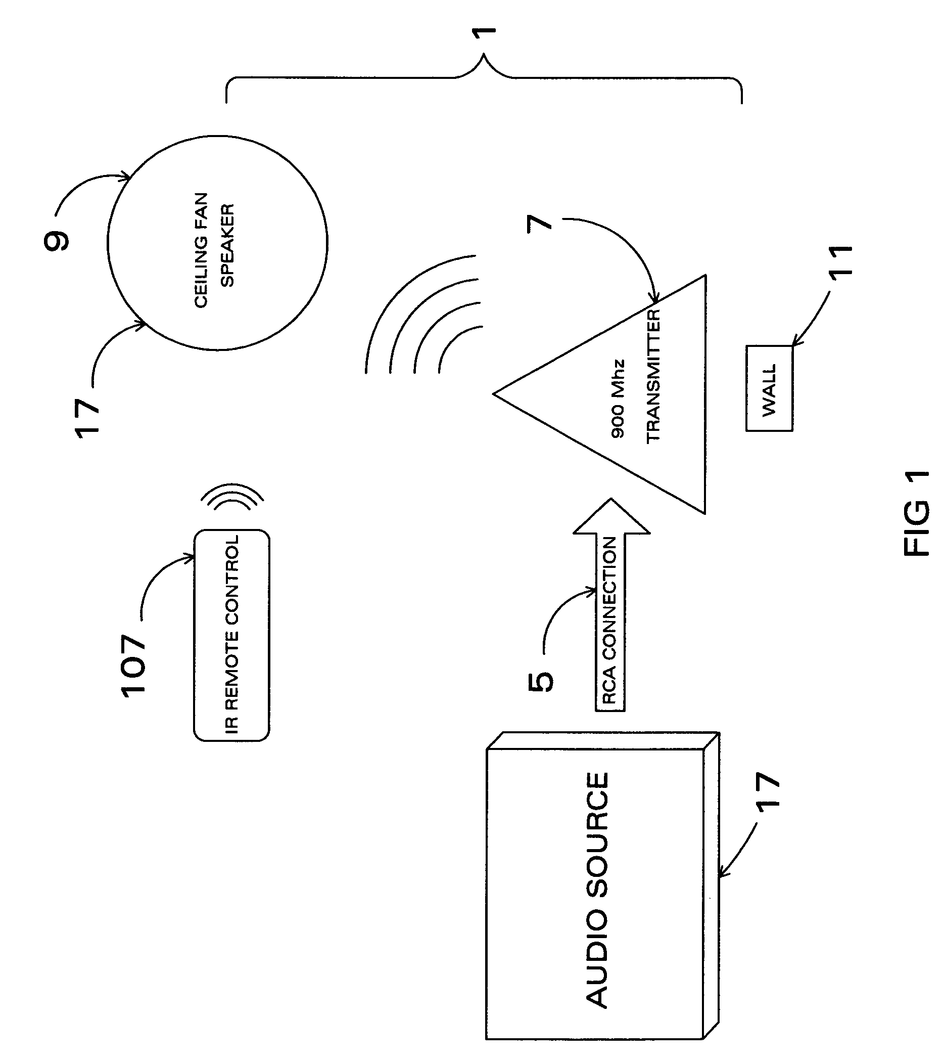
[0029]Referring to FIG. 2, the wireless receiver (also referred to as “RF Receiver”) 9 is located within the ceiling fan housing member 13. The audio source generator 3 and the transmitter 7 are located distal from the wireless receiver 9. The amplifier 15 and the speakers 17, are also located in the ceiling fan housing member 13. The speakers 17 are enclosed by a speaker housing member 19 that consists of an upper surface 21 and a lateral surface 23.

[0030]Referring to FIGS. 3, 4A, 4B and 4C, the speakers 17, in this first embodiment, consist of a bass speaker 63, a mid-range speaker 65 and a tweeter 67. Each speaker 17 has a sound grid 89 located on the outer surface 90 of the respective speakers 17. The speakers may be virtually any suitable shape and siz...

second embodiment

[0035]Referring to FIG. 7, a view from below of a fully assembled ceiling fan with the present invention installed thereon is visible. One particular design of this second embodiment is visible thereon, that being the speaker enclosure dome 143. The speaker enclosure dome houses the rear components of the speaker, and may optionally do so in an aesthetically pleasing manner. The receiver 9, amplifier 15, and remote control input 61 are among the components housed therein. The speaker enclosure dome 143 may be any suitable shape, but is preferably hemispherical or conical-frustral.

[0036]Referring to FIGS. 8, 9, 10, 11, and 12 collectively, several views of the ceiling fan housing member 13 of this second embodiment are visible. The globe 27 and the hardware associated therewith is not present in this second embodiment, and has been replaced by additional components, including a mounting bracket 145, an optional plate cover 147, one or more posts 149, and an optional screen 151. As ca...


PUM


Abstract

A multi-channel wireless speaker system to be used with ceiling fans wherein the audio source generator can be one of many medias, not limited by the following: television, stereophonic, monophonic, video game, home theater, public address system or security system. The audio source generator sends an audio signal to the transmitter that in turn relays the audio signal to the wireless receiver located in the ceiling fan housing member. The ceiling fan housing member includes speakers, and a light source if desired. The speakers produce an omni directional sound due to their unique positioning within the ceiling fan. The wireless speaker system is powered by the existing voltage available to the ceiling fan, so no new wiring is required to install the speaker system. The speaker settings are manipulated via a remote control.

Description

[0001]This application is a Continuation-In-Part of U.S. patent application Ser. No. 10 / 928,695, filed on Aug. 26, 2004 now abandoned, which was published as U.S. Patent Application Publication No. US2005 / 0078837 on Apr. 14, 2005, which claims the benefit of U.S. Provisional Application No. 60 / 510,745, filed Oct. 11, 2003.INTRODUCTION[0002]This invention relates to a wireless speaker system configured for use with ceiling fans. The invention facilitates the ability to listen or play centrally-located sound without the need for a stand or table.BACKGROUND OF THE INVENTION[0003]Generally, audio speaker systems are maintained within their own physical housing, although, in recent years the popularity of placing speakers within other household structures and electronics has risen. The purpose of such a combination is to combine the functions of cooling and audio systems in one decorative, space saving location. Wireless transmission, particularly at or around 900 MHz, has enabled audio ...

Claims


Application Information

Patent Timeline
Patent Type & Authority Patents(United States)
IPC IPC(8): H04R1/02H04R9/06
CPCH04R1/025H04R2201/021
Inventor HORNBACK, CHARLES
Owner CB LLC
Learn More