
Identifying a potential breakpoint location in a code path in a computer program based upon the frequency of execution of the code path as identified in collected profile data

a technology of profile data and code path, applied in the field of breakpoints for debugging computer programs, can solve the problems of identifying the location of breakpoints, halting the execution of the program, and stepping through hundreds or thousands of program instructions, etc., and achieve the effect of more efficient debugging

Inactive Publication Date: 2012-07-10
IBM CORP
View PDF15 Cites 18 Cited by
  • Summary
  • Abstract
  • Description
  • Claims
  • Application Information

AI Technical Summary

Benefits of technology

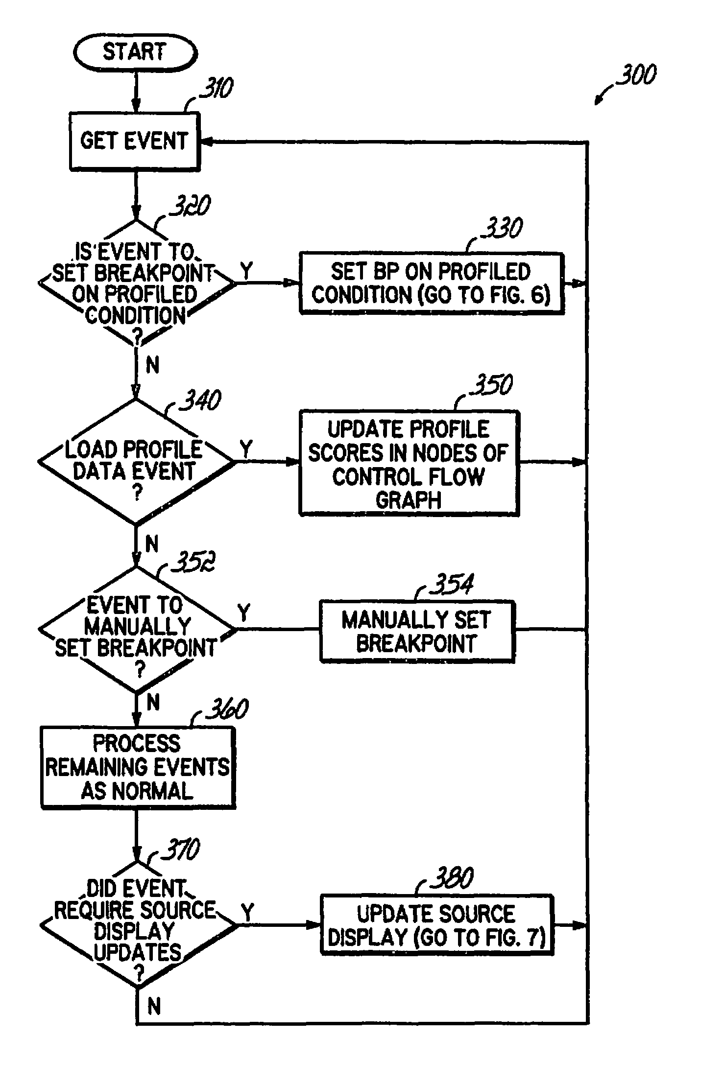
The invention is an apparatus, program product, and method that identify potential breakpoint locations in a computer program based upon the frequency of execution of the code path. This helps to efficiently identify and set breakpoints in areas that are more likely to assist in debugging the program. The invention can collect profile data for a computer program to identify frequencies of execution for a plurality of code paths and identify at least one potential breakpoint location in a code path. This can lead to more efficient debugging and improved program performance.

Problems solved by technology

While the step operation provides a programmer with a large amount of information about a program during its execution, stepping through hundreds or thousands of program instructions can be extremely tedious and time consuming, and may require a programmer to step through many program instructions that are known to be error-free before a set of instructions to be analyzed are executed.
Most breakpoints supported by conventional debuggers are unconditional, meaning that once such a breakpoint is reached, execution of the program is always halted.
However, one significant drawback of utilizing breakpoints is the identification of locations to set the breakpoints.
Although a programmer can sometimes identify a “good” breakpoint location based upon his or her familiarity with the computer program's code and / or error conditions, oftentimes a programmer is not familiar with the computer program that he or she is trying to debug.
For instance, the code of the program may have been written by a colleague, and as such, it may be difficult to identify a good location for a breakpoint other than by chance.
This is problematic because some instructions in a computer program are executed fairly often for different purposes, and incorrect placement of breakpoints may result in many needless stoppages before a desired stoppage is encountered.
This problem is especially pronounced in object-oriented programming (OOP) and other highly modular languages, where a single general purpose portion of a computer program may be executed in a number of different situations for different purposes.
Some general purpose objects in a computer program, in particular, may have routines that are called by many different objects, and thus placing a breakpoint in a routine of such an object may result in hundreds of unwanted stoppages prior to occurrence of a desired stoppage.
A computer programmer may be able to alleviate this problem to some extent by relocating the breakpoints but this is also typically a tedious and time-consuming process.
In addition to the delay and waste in time and / or resources that may be caused by these unwanted stoppages, a large number of unwanted stoppages are also problematic because it may indicate that this code path (i.e., series of instruction in order of execution) is a frequently executed code path in the computer program, also known as a “hot path”.
However, the bugs in a computer program are oftentimes associated with a code path that is infrequently executed, also known as a cold path; otherwise, the bug would have already been encountered and resolved much earlier in the development process.
Even the identification of good locations to set conditional breakpoints, as opposed to unconditional breakpoints, is problematic.
However, once again, unless the programmer knows of a specific condition to utilize, for example, based upon his or her familiarity with the computer program, and the condition is sufficiently unique, the programmer may also be faced with hundreds of unwanted stoppages.

Method used


Image

  • Identifying a potential breakpoint location in a code path in a computer program based upon the frequency of execution of the code path as identified in collected profile data
  • Identifying a potential breakpoint location in a code path in a computer program based upon the frequency of execution of the code path as identified in collected profile data
  • Identifying a potential breakpoint location in a code path in a computer program based upon the frequency of execution of the code path as identified in collected profile data

Examples


Embodiment Construction

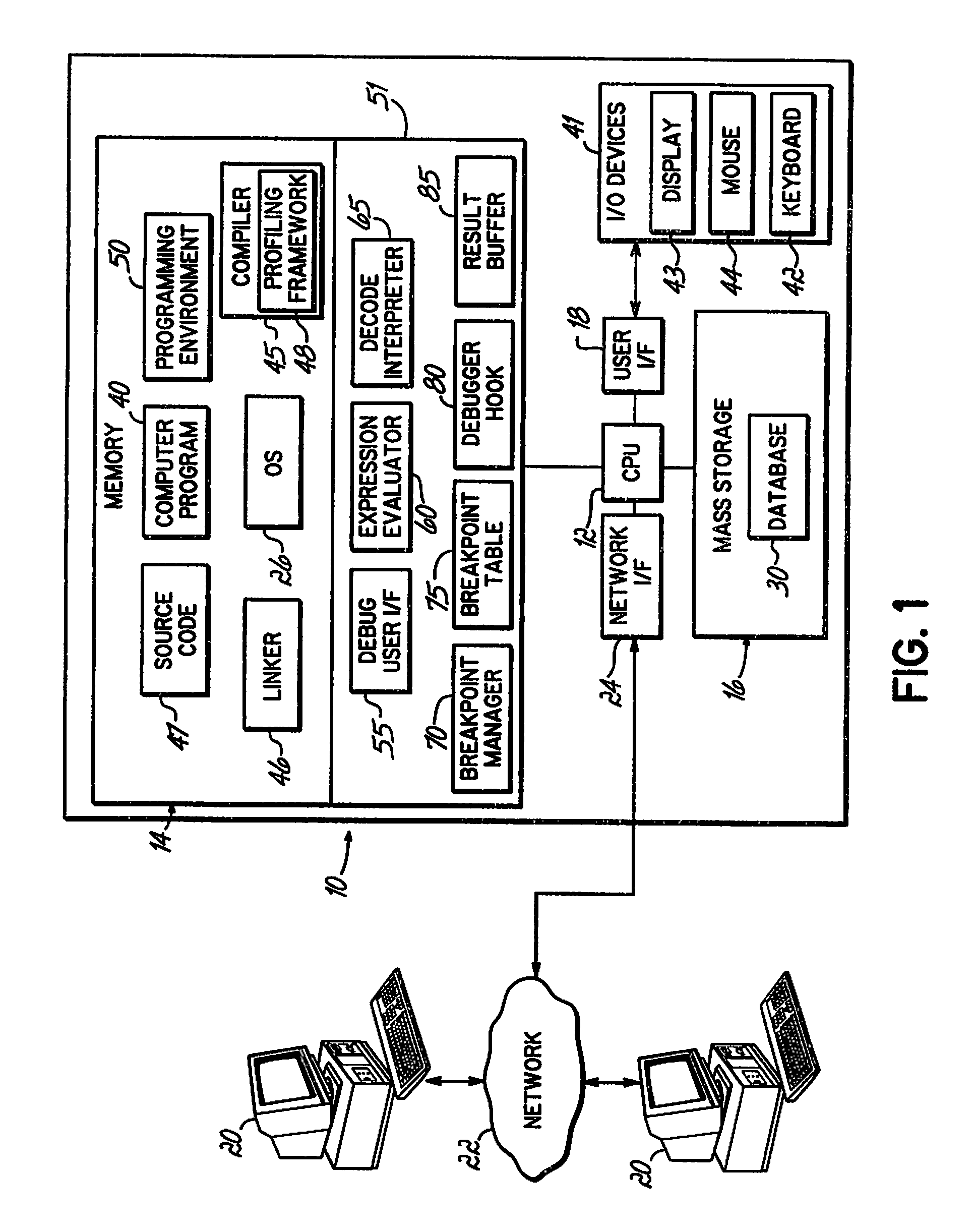
[0021]Turning now to the Drawings, wherein like numbers denote like parts throughout the several views, FIG. 1 illustrates an exemplary hardware environment for an apparatus 10 for implementing the identification of breakpoint locations consistent with the invention. For the purposes of the invention, apparatus 10 may represent practically any type of computer, computer system or other programmable electronic device, including a client computer, a server computer, a portable computer, a handheld computer, an embedded controller, etc. Moreover, apparatus 10 may be implemented using one or more networked computers, e.g., in a cluster or other distributed computing system. Apparatus 10 will hereinafter also be referred to as a “computer,” although it should be appreciated that the term “apparatus” may also include other suitable programmable electronic devices consistent with the invention.

[0022]Computer 10 typically includes a central processing unit (CPU) 12 including one or more mic...


PUM


Abstract

An apparatus, program product and method identify a potential breakpoint location in a code path in a computer program based upon the frequency of execution of the code path as identified in collected profile data. By doing so, a potential breakpoint location may be identified for an infrequently executed code path and / or a frequently executed code path, and a breakpoint may be set at the identified breakpoint location. As such, breakpoints may be set in locations that may be more likely to assist a user in debugging the computer program and may result in more efficient debugging.

Description

FIELD OF INVENTION[0001]The invention is directed to debuggers and debugging of computer programs. In particular, the invention is generally related to breakpoints for debugging computer programs and the like.BACKGROUND OF THE INVENTION[0002]Locating, analyzing and correcting suspected faults or bugs in a computer program is a process known as “debugging.” Typically, a programmer uses another computer program commonly known as a “debugger” to debug a program under development.[0003]Conventional debuggers typically support two primary operations to assist a computer programmer. A first operation supported by conventional debuggers is a “step” function, which permits a computer programmer to process instructions (also known as “statements”) in a computer program one-by-one, and see the results upon completion of each instruction. While the step operation provides a programmer with a large amount of information about a program during its execution, stepping through hundreds or thousand...

Claims


Application Information

Patent Timeline
Patent Type & Authority Patents(United States)
IPC IPC(8): G06F9/44
CPCG06F11/3612G06F11/3636
Inventor BATES, CARY LEESCHROEDER, MARK DOUGLAS
Owner IBM CORP
Learn More