Electron beam irradiation of bulk material solids

a technology of electron beam and bulk material, which is applied in the direction of packaging goods, liquid handling, applications, etc., can solve the problems of inefficiency in this process, loss of efficiency in the irradiation technique of the tray, and inability to process more efficiently

Active Publication Date: 2012-07-17
E BEAM SERVICES
View PDF22 Cites 4 Cited by
  • Summary
  • Abstract
  • Description
  • Claims
  • Application Information

AI Technical Summary

Benefits of technology

[0020]One objective of this invention is to efficiently handle bulk material solids for electron beam processing. Another objective is to electron beam process bulk material solids and environmentally control the process. Environmental control is achieved by packaging the bulk material solids in an essentially solid form of a container for electron-beam processing. The bulk material solids are held within the container and undesired environmental effects are avoided by processing the materials within the container. The inventive technique avoids inefficient electron beam processing and / or unnecessary processing steps which have heretofore been practiced in the prior art, such as multiple exposures to doses of radiation and stirring the bulk material solids between exposures as in U.S. Pat. No. 5,916,929. The invention also eliminates expensive, time-consuming and inefficient operations. The container of bulk material solids is shaped for control of the radiation dose. The previous problems with depth-dose efficiency losses are reduced by the advantageous effects of the 2-sided electron-beam processing of the package. Furthermore, the bulk material solids in the package during and after processing can be handled effectively and conveniently, and such handling advantages can be enjoyed in subsequent treatment steps in certain applications. The packaging, preferably, is a plastic film which can be easily disposed of or is potentially reusable or recyclable. Alternatively, re-usable containers with rigid formed sides with gas impermeable sheet material on opposed faces may be used. Other advantages of the method include the elimination of expensive equipment of known methods such as environmentally-controlled chambers, fluidized beds, mixing and / or handling equipment, dust and pollution control equipment, etc. In addition, the potential for contamination with open-traveling beds, or with the prior art technique of tray irradiation, is avoided. More control over the bulk material solids being processed is achieved with the packaging technique of this invention and 2-sided electron-beam radiation.
[0021]Additional advantages and objectives of this invention will be understood with reference to the Drawings and following Examples.

Problems solved by technology

Inefficiencies in this process are due to overscan of the trays with the e-beam and the penetration characteristics (depth-dose) of the electron beam.
The latter efficiency loss in the tray irradiation technique arises out of the fact that the dose received by the layer of material varies with its depth.
This inefficiency, i.e., the depth-dose characteristic, can cause processing inefficiency of more than 50%, and in some instances may result in undesirable properties in the resulting product.

Method used


Image

  • Electron beam irradiation of bulk material solids
  • Electron beam irradiation of bulk material solids
  • Electron beam irradiation of bulk material solids

Examples


example 1

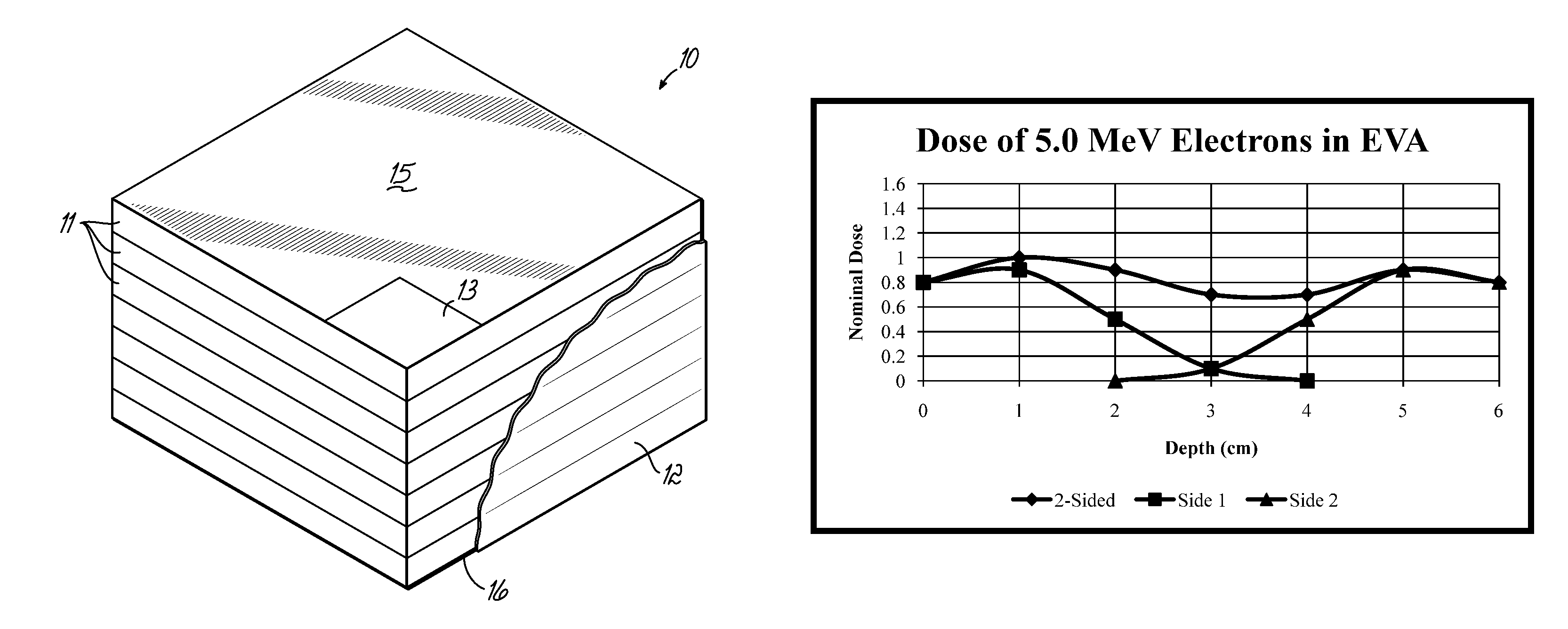
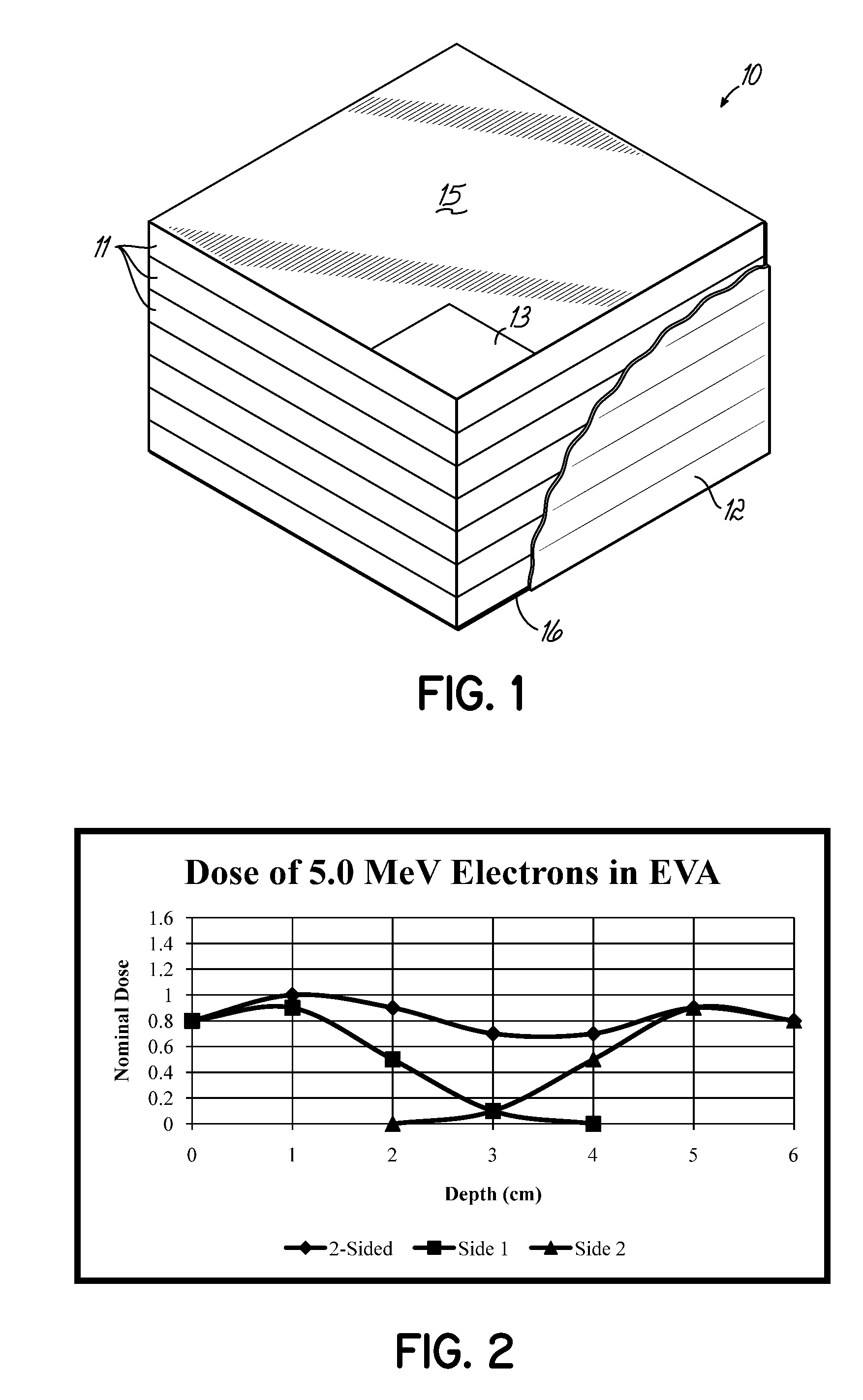
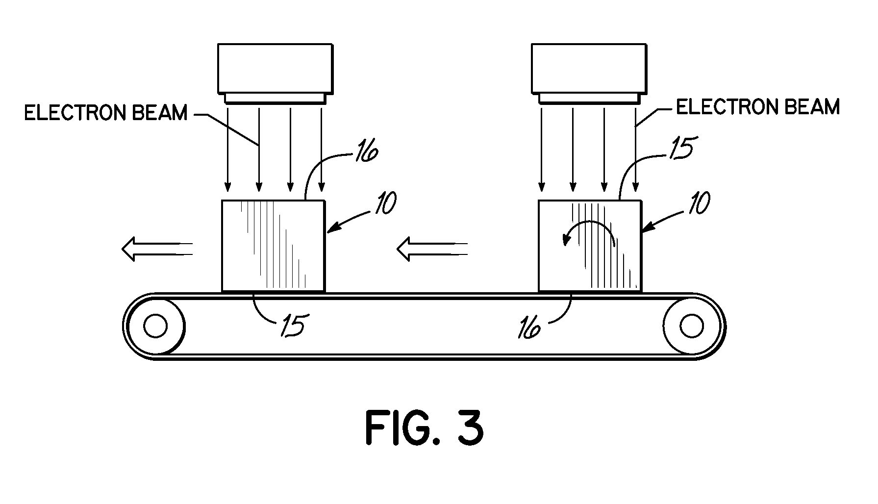
[0022]An example of the application of electron beam irradiation of bulk material solids is the irradiation of ethylene vinyl acetate polymer (EVA) material. In this case the purpose of the radiation is to modify the melt flow rate property of the material from a high starting point, such as is typically produced by the high-volume reactor, into a precise, but lower melt flow rate for a particular end-product requirement. In this example the starting melt flow rate of the EVA material was 16 dg / min (ASTM D1238), and the melt flow rate of the finished product after irradiation was 0.5-1.0 dg / min. The electron beam irradiation would customarily be accomplished in one pass of a relatively thin bed of loose pellets on a horizontal conveyor. However, in this example the EVA pellets were formed into a package made entirely of thin film, such that the loose bulk material became a substantially solid rectangular block, and then the first and second opposed sides were irradiated perpendicula...

example 2

[0025]Another example of the application of electron beam irradiation of bulk material solids is the irradiation of substantially linear polypropylene material. In this case the purpose of the irradiation is to modify the molecular structure of the material by creating long-chain branching. This long-chain branching increases the melt-strength of the material, thereby extending the use of the polypropylene into more applications. The starting material had a melt strength of 2-3 cN and a melt flow rate of 0.7 dg / min (ASTM D1238). Customarily the process of increasing the melt strength of polypropylene consists of irradiation and heat-treatment of the polymer in a low oxygen atmosphere (U.S. Pat. No. 4,916,198). To accomplish this, in customary practice, the loose polypropylene pellets are processed in a thin bed of pellets under the beam and then conveyed into a fluid-bed oven to heat treat the polymer, using large and complex equipment in part due to the need to create and maintain ...

example 3

[0028]Another example of irradiating bulk material solids is in the irradiation of polytetrafluoroethylene (PTFE) flake or scrap material. In this case the purpose of the irradiation was to reduce the molecular weight of the PTFE to enable the subsequent milling of the PTFE into a fine powder. Without the irradiation of the PTFE, milling is very difficult due to the inherent high mechanical strength of the unirradiated polymer. The PTFE material can be placed in a reusable four-sided stainless steel container frame and utilizing stainless steel foil of 0.38 mm thickness on opposed faces. Using this methodology, the PTFE can be processed without creating a dust nuisance from the creation of powder during the irradiation as occurs in customary processing, for example as in U.S. Pat. No. 5,916,929 (Knobel and Minbiole). In this example, the material was processed on the first and second opposed faces, perpendicular to the beam of electrons for two-sided processing. After the irradiatio...


PUM

PropertyMeasurementUnit
thicknessaaaaaaaaaa
thicknessaaaaaaaaaa
melt flow rateaaaaaaaaaa

Abstract

Bulk material solids are packaged in a shaped block and the packaged block is irradiated on two sides using high-energy electron beam radiation to uniformly irradiate the solids in the package.

Description

FIELD OF THE INVENTION[0001]This invention relates to a method of electron beam irradiation of bulk material solids using high-energy radiation to improve various physical and mechanical properties.BACKGROUND OF THE INVENTION[0002]Many types of products are created or improved by electron beam (e-beam) processing. Products include appliance parts, gaskets, manifolds, tubing, electrical connectors, molded parts, resin pellets, etc. The possibilities are endless because, in many polymers, property improvements can be attained through e-beam processing. Commodity resins and polymeric materials including polyethylene, ethylene vinyl acetate, polyvinyl chloride, polyamides, and certain types of rubber, such as neoprene, silicone, and ethylene-propylene rubbers, can all realize substantial property enhancement. Property improvements of these polymeric materials may include an increase in tensile strength, impact strength, abrasion resistance, chemical resistance, heat deflection, modulus,...

Claims


Application Information

Patent Timeline
Patent Type & Authority Patents(United States)
IPC IPC(8): B65B63/00
CPCB29B13/08C08J3/28B29C2035/0877
Inventor MINBIOLE, PAUL R.YASENCHAK, DANIEL F.KEENAN, DAVID W.
Owner E BEAM SERVICES
Why Eureka
Try Eureka