Underwater vehicle with sonar array

a sonar array and underwater vehicle technology, applied in underwater equipment, special-purpose vessels, instruments, etc., can solve the problems of complex terrain surrounding the vehicle on all sides, true three-dimensional navigation problems, and certain problems of traditional underwater vehicles

Active Publication Date: 2012-07-17
STONE AEROSPACE INC
View PDF4 Cites 20 Cited by
  • Summary
  • Abstract
  • Description
  • Claims
  • Application Information

AI Technical Summary

Benefits of technology

[0017]The present invention provides the necessary configuration for a vehicle wherein an internal algorithm can compare a “new” geometry to an “old” geometry collected earlier to construct a best fit of the new world map with the old world map and locate the vehicle within the context of the new world map. This then provides a completely independent mechanism for correction of the gradual drift in x and y that is not dependent on any form of external navigation aid.

Problems solved by technology

In such environments, complicated terrain frequently surrounds the vehicle on all sides.
As such, these conditions give rise to certain problems for traditional underwater vehicles.
First, labyrinthine environments create a true three-dimensional navigation problem for AUVs.
Because of the presence of these surfaces, it is very unlikely, if not impossible, to obtain continuous or even periodic navigational updates from external navigation sources.
In a complex labyrinthine environment, however, the net result would simply be the permanent loss of the very-expensive vehicle.
Traditional AUVs suffer from one additional, and frequently fatal, design flaw for working in labyrinthine environments: They are almost always torpedo shaped—that is, they almost always have long, cylindrical bodies, blunt nose cones, and a single, aft propeller.
AUVs have been lost in such environments and never recovered.
Navigational failure in a complicated 3D environment cannot be dismissed when designing a high reliability system to work in such localities.
The possible failure of torpedo-architecture AUVs in a labyrinthine environment can be attributed to many factors including lack of complete geometric knowledge of its environment (due to limited geometric sensor capabilities), lack of maneuverability (due to its long shape and aft propulsion package and therefore long turning radius), and failure of any of many single-point systems (e.g. the propeller prop becoming snagged), among many others.
While indispensible for bathymetric surveying of essentially 2½ D ocean floor topography, they are bulky instruments that cannot effectively (both physically and from a cost perspective) cover a 4π steradian solid viewing angle about a vehicle.
Further, in a labyrinthine environment, these approaches are particularly susceptible to multipath spoofing and will therefore generate false input data leading to loss of pose lock.
These devices, however, rely on a reasonable degree of phase coherence to operate and multipath returns from a labyrinthine environment serve to corrupt phase coherence.

Method used


Image

  • Underwater vehicle with sonar array
  • Underwater vehicle with sonar array
  • Underwater vehicle with sonar array

Examples


Embodiment Construction

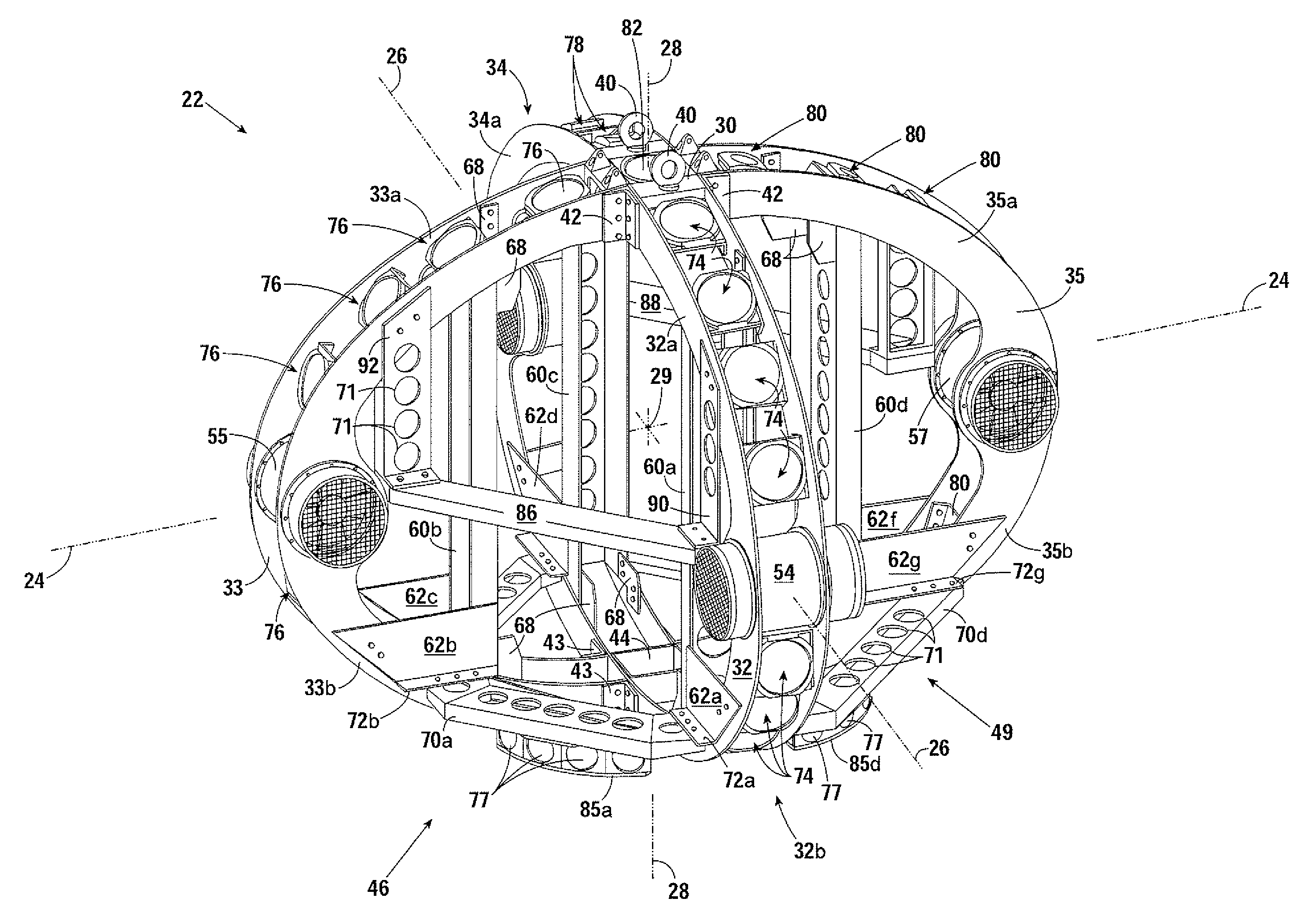
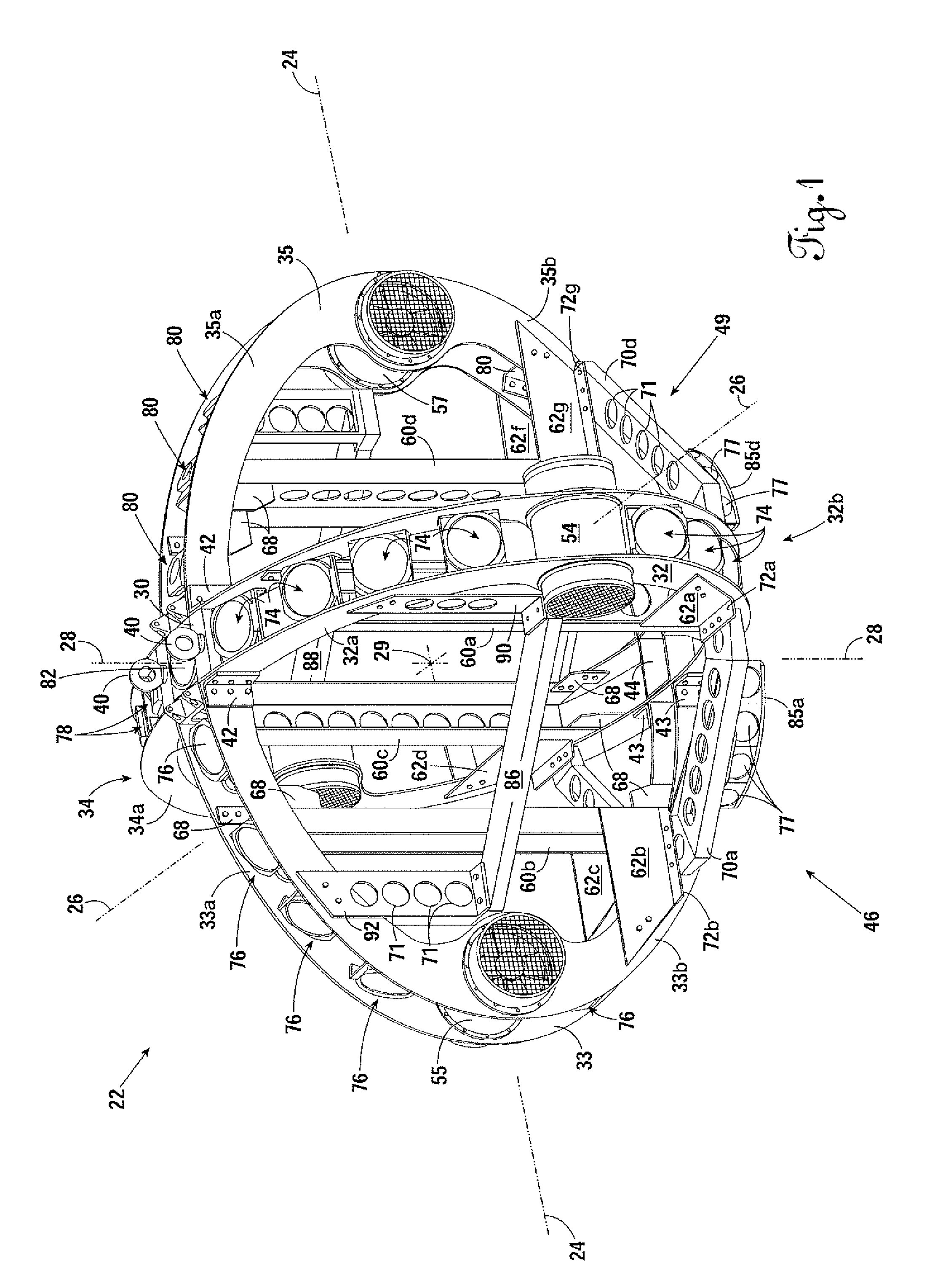
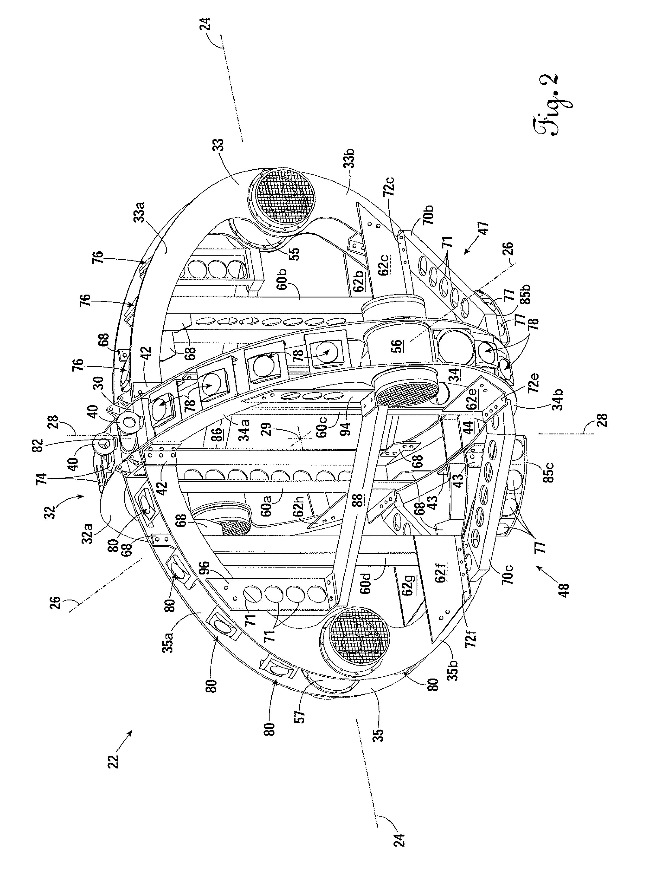
[0032]FIG. 1 and FIG. 2 are an isometric top front view and an isometric top rear view, respectively, of the axi-symmetric framing system 22 of the preferred embodiment of the present invention. The axi-symmetric framing system 22 is described with reference to an x-y-z coordinate system having an x-axis 24, a y-axis 26, and a z-axis 28, such that rotation of the framing system 22 about the z-axis 28, or “centerline,” which intersects with the center 29 of the framing system 22, defines a uniformly-convex shell of revolution. By containing the subsystems and science payload of the vehicle within this shell of revolution, the vehicle has no “port,”“starboard,”“bow,” nor “stern,” and thus can maneuver at will in the yaw degree of freedom—that is, rotation about the centerline 28 that generated the shell of revolution. Moreover, a uniformly-convex topology serves to reduce possible catch points on the vehicle—thus, spheres, oblate spheroids, ellipsoids and even cylinders with rounded e...


PUM


Abstract

An underwater vehicle including an axi-symmetric framing system rotatable about a centerline to define a shell of revolution having a uniformly-convex outer boundary. A narrow-beam sonar array is mounted on the axi-symmetric framing system, and includes a multitude of simultaneously-fireable and / or asynchronously-fireable transducers distributed substantially evenly over a 4π-steradian viewing angle. The present invention provides the necessary configuration for a vehicle wherein an internal algorithm can compare a “new” geometry to an “old” geometry collected earlier to construct a best fit of the new world map with the old world map and locate the vehicle within the context of the new world map. This then provides a completely independent mechanism for correction of the gradual drift in x and y that is not dependent on any form of external navigation aid.

Description

CROSS-REFERENCES TO RELATED APPLICATIONS[0001]This original nonprovisional application claims the benefit of U.S. provisional application No. 60 / 953,070, filed Jul. 31, 2007 and entitled “Autonomous Underwater Vehicle for 3D Mapping and Navigation in Labyrinthine Environments,” which is incorporated by reference herein.STATEMENT REGARDING FEDERALLY SPONSORED RESEARCH OR DEVELOPMENT[0002]The U.S. Government has a paid-up license in this invention and the right in limited circumstances to require the patent owner to license others on reasonable terms as provided for by the terms of Grant No. NNG04GC09G awarded by the National Aeronautics and Space Administration.BACKGROUND OF THE INVENTION[0003]1. Field of the Invention[0004]The present invention relates to the exterior geometry and structural configuration for an underwater vehicle. More specifically, the invention relates to the shape of the vehicle in combination with the positioning of a plurality of sonar devices on the exterior ...

Claims


Application Information

Patent Timeline
Patent Type & Authority Patents(United States)
IPC IPC(8): B63G8/39G01S15/93
CPCB63C11/42G01S7/521G01S15/93G01S15/8922B63B3/13
Inventor STONE, WILLIAM C.HOGAN, BARTHOLOMEW P.
Owner STONE AEROSPACE INC
Why Eureka
Try Eureka