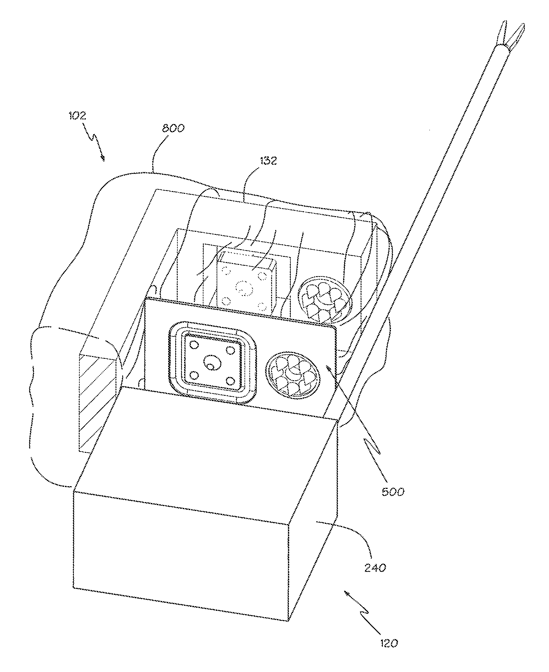
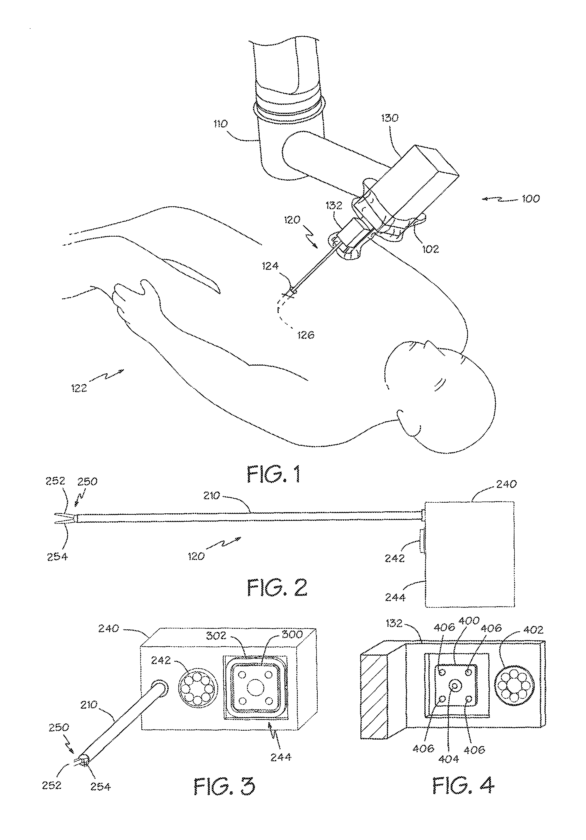
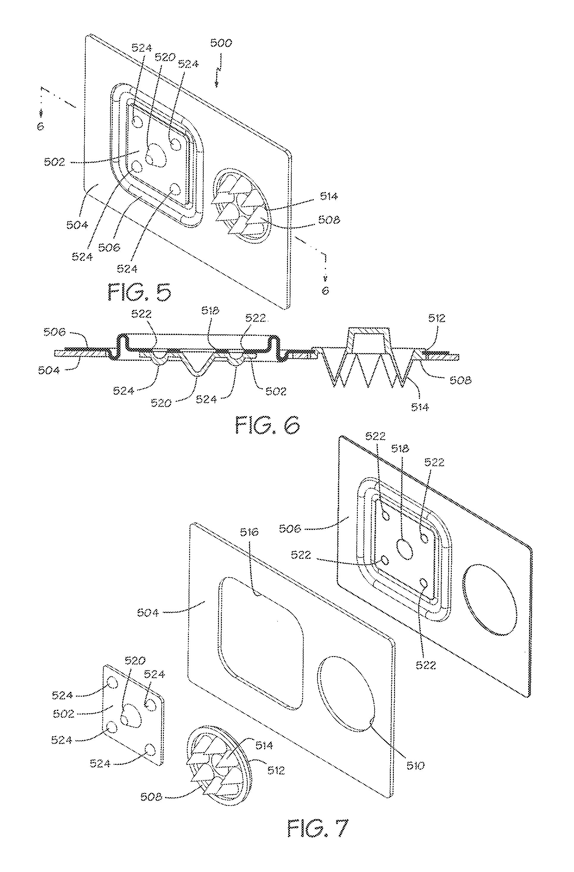
Sterile drape interface for robotic surgical instrument

a robotic surgical instrument and drape technology, applied in the field of surgical drapes, can solve the problems of contaminated robot manipulators, inability to sterilize the electrical connections, and the inability of servo motors, encoders and electrical connections that are necessary to robotically control the motors,

Active Publication Date: 2012-07-17
INTUITIVE SURGICAL OPERATIONS INC
View PDF9 Cites 1354 Cited by
  • Summary
  • Abstract
  • Description
  • Claims
  • Application Information

AI Technical Summary

Problems solved by technology

One such challenge results from the fact that a portion of the electromechanical robotic surgical manipulator will be in direct contact with the surgical instruments, and will also be positioned adjacent the operation site.
Accordingly, the robotic manipulator may become contaminated during surgery and is typically disposed of or sterilized between operations.
However, the servo motors, sensors, encoders and electrical connections that are necessary to robotically control the motors typically cannot be sterilized using conventional methods, e.g., steam, heat and pressure or chemicals, because they would be damaged or destroyed in the sterilization process.
Another challenge with robotic surgery systems is that a surgeon will typically employ a large number of different surgical instruments during a procedure.
Since the number of instrument holders are limited due to space constraints and cost, many of these surgical instruments will be attached and detached from the same instrument holder a number of times during an operation.
In laparoscopic procedures, for example, the number of entry ports into the patient's abdomen is generally limited during the operation because of space constraints as well as a desire to avoid unnecessary incisions in the patient.
Likewise, in open surgery, there is typically not enough room around the surgical site to position more than one or two surgical manipulators, and so the surgeon's assistant will be compelled to frequently remove instruments from the robotic manipulator and exchange them with other surgical tools.

Method used


Image

  • Sterile drape interface for robotic surgical instrument
  • Sterile drape interface for robotic surgical instrument
  • Sterile drape interface for robotic surgical instrument

Examples


Embodiment Construction

[0026]In the following description, numerous specific details are set forth. However, it is understood that embodiments of the invention may be practiced without these specific details. In other instances, well-known circuits, structures and techniques have not been shown in detail in order not to obscure the understanding of this description.

[0027]In the following description, reference is made to the accompanying drawings, which illustrate several embodiments of the present invention. It is understood that other embodiments may be utilized, and mechanical compositional, structural, electrical, and operational changes may be made without departing from the spirit and scope of the present disclosure. The following detailed description is not to be taken in a limiting sense, and the scope of the embodiments of the present invention is defined only by the claims of the issued patent.

[0028]The terminology used herein is for the purpose of describing particular embodiments only and is n...


PUM


Abstract

A robotic surgical system includes a sterile surgical instrument, a robotic surgical manipulator, and a sterile drape covering at least a portion of the robotic surgical manipulator. The surgical instrument has a proximal interface and a distal end effector. The proximal interface includes a gimbal assembly with two intersecting rotational axes coupled to the distal end effector. The robotic surgical manipulator has a drive plate that bears against the gimbal assembly. The drive plate has two degrees of rotational freedom about a center of motion that is coincident with an intersection of the axes of the gimbal assembly. The sterile drape includes a sterile sheet covers at least a portion of the robotic surgical manipulator, a frame bonded to the sterile sheet, an instrument interface that covers the drive plate of the robotic surgical manipulator, and a diaphragm that connects the instrument interface to the frame.

Description

[0001]This application is a continuation of U.S. patent application Ser. No. 12 / 060,084 (filed Mar. 31, 2008; now U.S. Pat. No. 7,886,743 A1), which is hereby incorporated by reference in its entirety.BACKGROUND[0002]1. Field[0003]Embodiments of the invention relate to the field of surgical drapes; and more specifically, to surgical drapes for robotic manipulators with provisions for transferring motion to attached surgical instruments.[0004]2. Background[0005]Minimally invasive medical techniques have been used to reduce the amount of extraneous tissue which may be damaged during diagnostic or surgical procedures, thereby reducing patient recovery time, discomfort, and deleterious side effects. Traditional forms of minimally invasive surgery include endoscopy. One of the more common forms of endoscopy is laparoscopy, which is minimally invasive inspection or surgery within the abdominal cavity. In traditional laparoscopic surgery, a patient's abdominal cavity is insufflated with ga...

Claims


Application Information

Patent Timeline
Patent Type & Authority Patents(United States)
IPC IPC(8): A61B19/08A61B1/00
CPCA61B19/081A61B19/2203A61B2019/2242A61B2017/00477A61B34/71A61B34/30A61B46/10A61B46/00A61B50/00A61B90/00B25J19/06
Inventor COOPER, THOMAS G.RAMSTAD, CRAIG R.
Owner INTUITIVE SURGICAL OPERATIONS INC
Why Eureka
Try Eureka