
Phantom power saver power tap

a power tap and phantom technology, applied in the direction of electrical discharge lamps, coupling device connections, switchgear with withdrawable carriages, etc., can solve the problems of reducing the utility of a three to one or six to one power tap, metal receptacles are covered or smothered, and the disadvantage of large size of power taps, so as to reduce electricity production and consumption, eliminate the consumption of phantom power, and reduce the effect of electricity costs for consumers

Inactive Publication Date: 2012-07-17
ONPLUG INNOVATIONS
View PDF16 Cites 9 Cited by
  • Summary
  • Abstract
  • Description
  • Claims
  • Application Information

AI Technical Summary

Benefits of technology

"The present invention is a power tap apparatus that can be used to switch off phantom power loads. It is designed to be attached to an electrical power source and an electronic device or power adapter. The apparatus has a compact size and can be easily installed and removed. It uses a printed circuit board with indicator functions to show that power is being consumed. The apparatus can be used with different types of electronic devices and can be installed in multiple outlets. It is designed to be a low-profile and aesthetically pleasing solution for use in homes. The technical effects of this invention include reducing electricity production and consumption, reducing green house gas production, and reducing electricity costs for consumers."

Problems solved by technology

These types of power taps have the disadvantage of large size whereby the power tap may plug into an electrical wall outlet and cover over the adjacent outlet.
Another disadvantage is that some of the metal receptacles are covered or smothered by electrical plugs inserted or power adapters inserted.
This specific disadvantage reduces the utility of a three to one or six to one power tap.
A further disadvantage is the lack of control of electrical conductivity between protruding male blades and female receptacles.
Additionally, a perfectly aligned vertical and horizontal male blades and female blades would cause the height of the power tap to increase in an inefficient manner.
As a result the assembly of the power tap becomes larger or the assembly would become less reliable with a higher risk of inadvertent contact between male and female blades causing increased risk of electrical shock.
This problem is exacerbated by the burning of fossil fuels to generate electricity.
Where there is no measureable benefit or wasted power or lost electrical power no environmental side effects can be tolerated.
It is commonly known that modern electronic and electrical devices and appliances consume electricity to perform their intended function.
What is not commonly known is that when these electronic and electrical devices and appliances are not performing their intended function, they continue to consume electricity as they have a standby mode that consumes what is less commonly known as phantom power or standby power.
This phantom power provides no useful benefit to the consumer.
These devices are often left unplugged to consume phantom power without providing a measureable benefit to their owners.
Power adapters and chargers use only a small amount of electricity when in standby mode but it is commonly known that there are hundreds of millions of these in use around the world and collectively they contribute to a sizeable waste of electricity.
Many disclosed power adapters and chargers have been designed to reduce power consumption but not eliminate all standby power.
The disadvantage of standby power detection and automatic shut off is that they have increased points of failure, increased cost, and a larger footprint where these attributes are not desirable.
The problems are that many people find unplugging inconvenient and many switches do not turn off the appliance off in its entirety.
Conventional Power taps, power strips and power adapters with automatic detection and automatic shut off or automatic disconnect or power taps operated by remote controls introduce more points of failure and often consume electrical power in the power detection stage and in the power disconnect stage.

Method used


Image

  • Phantom power saver power tap
  • Phantom power saver power tap
  • Phantom power saver power tap

Examples


Embodiment Construction

[0042]Apparatus Aspect

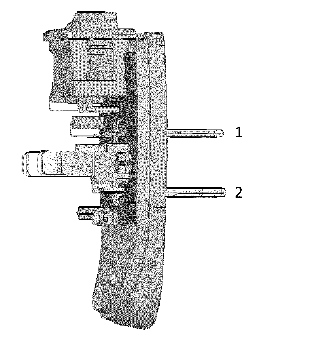
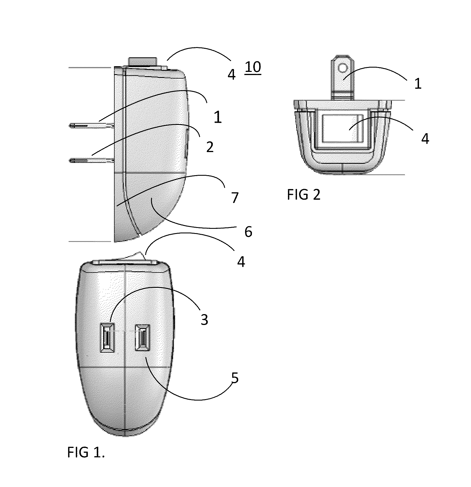
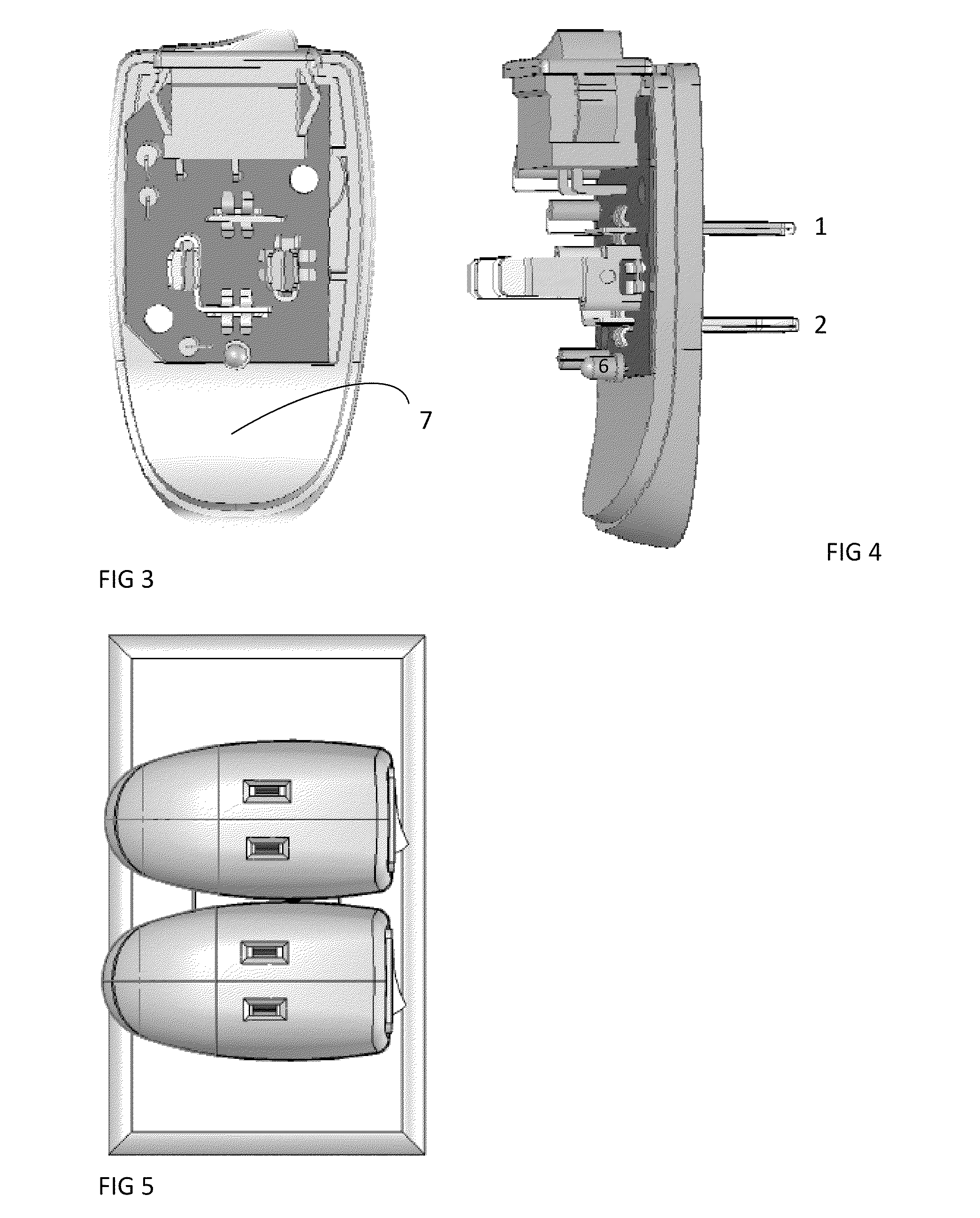
[0043]Referring to FIG. 1 showing a first preferred embodiment of the phantom power saver switch power tap in accordance with the present invention, the power tap 10 includes a first insulation casing 6 and a second insulation casing 7 coupled to the first insulation casing 6 to form a closed space to receive a printed circuit board 8, a pair of conductive male blades 1,2, a pair of conductive female receptacles as accessed through holes 3,5 and a switch 4 therein.

[0044]The second insulation casing 7 defines a receiving space to seat the printed circuit board where the male blades 1, 2 pass though rectangular holes 11,12 to form a pair of male electrical plug blades external to insulation casing 7, leaving the printed circuit board seated in receiving space of insulation casing 7.

[0045]The printed circuit board defines a pair of male blades 1,2 visible externally to insulation casing 7 and a pair of receiving female receptacle holes 3,5. The male blades 1,2 ext...


PUM


Abstract

An apparatus, system and method are disclosed for eliminating phantom power wastage utilizing a power tap. An insulation casing creates a receiving space for a printed circuit board which mounts male blades, female receptacles, phantom power indication and a mechanical electrical switching capability is disclosed. The conductive male blades and female receptacles create a cross pattern for a two pronged power tap that allows miniaturization of the power tap so as to allow full access to adjacent electrical outlets. Switching states include normally open which permits zero power flow and normally closed which permits power indication and allows power to flow from conductive male blades to conductive female receiving receptacles.

Description

CROSS REFERENCE TO RELATED APPLICATIONS[0001]This application claims the benefit of PPA Appl No. 61 / 181,407 filed on May 27, 2009.FIELD OF INVENTION[0002]The present invention generally relates to a power tap and more particularly to a switchable power tap capable of intervention in the consumption of standby power or phantom power through electrical and mechanical manual intervention.BACKGROUND OF THE INVENTION[0003]A conventional power tap (sometimes called current tap) includes a plastic electrical insulating case with metal plugs as inserts connected in a manner to fan out electricity from one electrical input to more than one electrical outputs. Conventionally this power is passed through the power tap unobstructed. Typically a power tap would have protruding metal blades. Equally the power tap would have cavities with metal receptacles that accept the insertion of metal blades from electrical plugs and power adapters. Power taps often use metal inserts to route electricity fro...

Claims


Application Information

Patent Timeline
Patent Type & Authority Patents(United States)
IPC IPC(8): H01R13/70
CPCH01R13/70H01R13/6658H01R31/065
Inventor HEFFERNAN, GERARD MARTIN
Owner ONPLUG INNOVATIONS
Learn More