Pellicle frame and lithographic pellicle
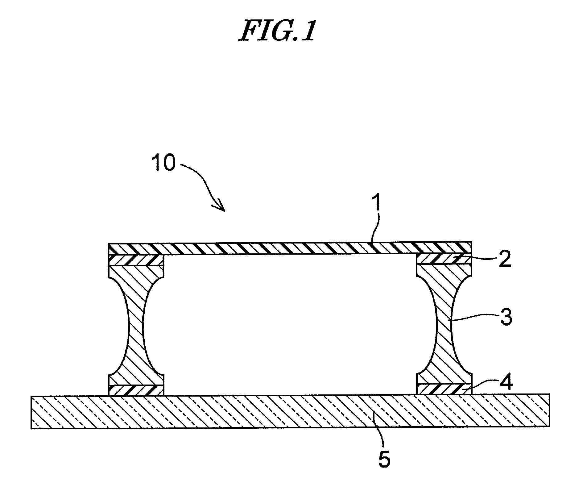
a lithographic and pellicle technology, applied in the field of lithographic pellicle and lithographic pellicle, can solve problems such as mask deformation, and achieve the effect of suppressing the deformation of the exposure master pla
- Summary
- Abstract
- Description
- Claims
- Application Information
AI Technical Summary
Benefits of technology
Problems solved by technology
Method used
Image
Examples
example 1
[0074]A 5% solution of Cytop CTX-S (product name, manufactured by Asahi Glass Co., Ltd.) dissolved in perfluorotributylamine was dropped on a silicon wafer and spread over the wafer by rotating the wafer at 830 rpm by a spin coating method. Subsequently, drying was carried out at room temperature (25° C.) for 30 minutes and then at 180° C., thus giving a uniform film. An aluminum framework coated with an adhesive was affixed thereto, and only the film was peeled off, thus giving a pellicle film. The required number of Cytop CTX-S films were prepared and used in Examples 1 to 10 and the Comparative Example.
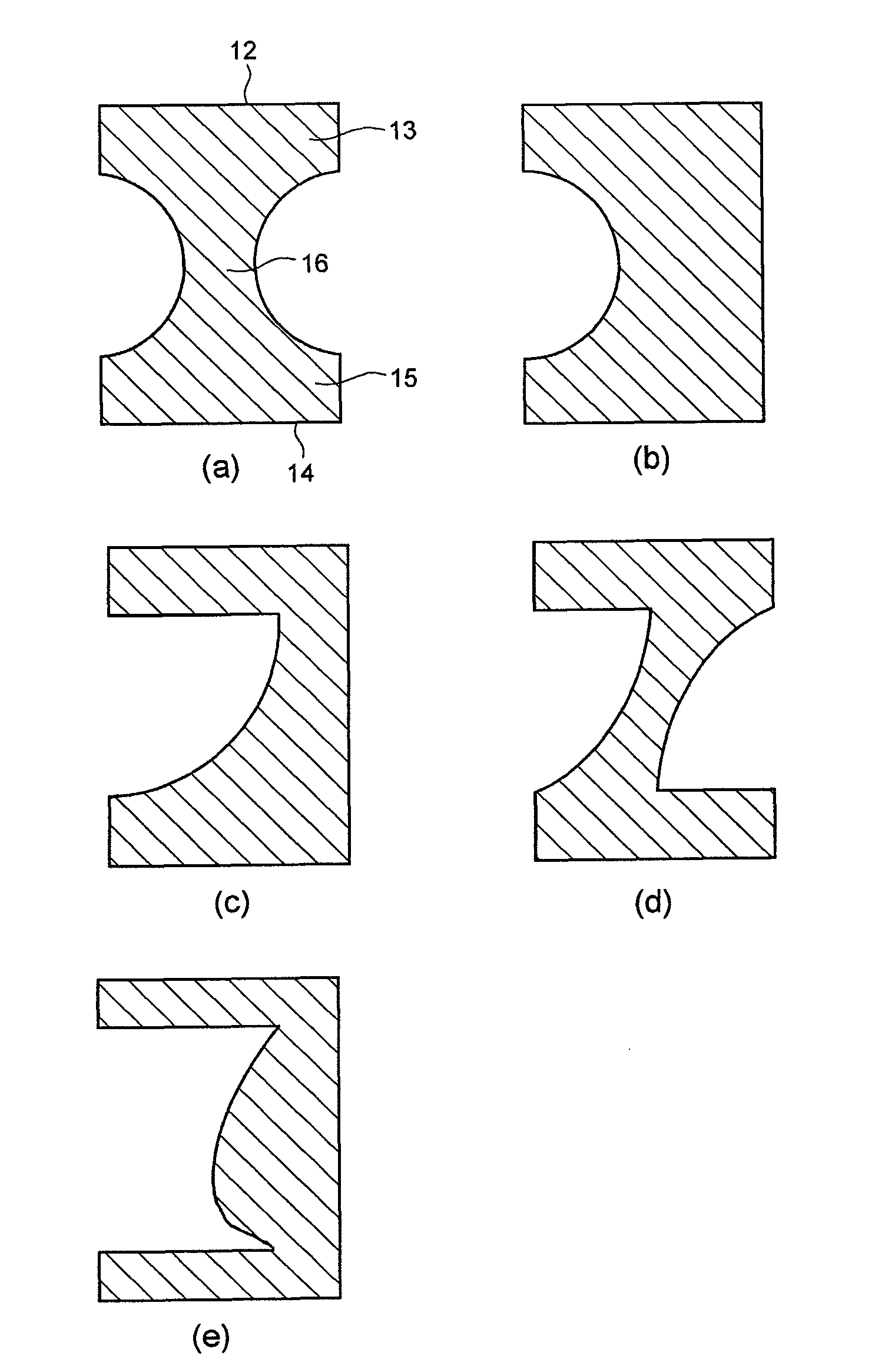
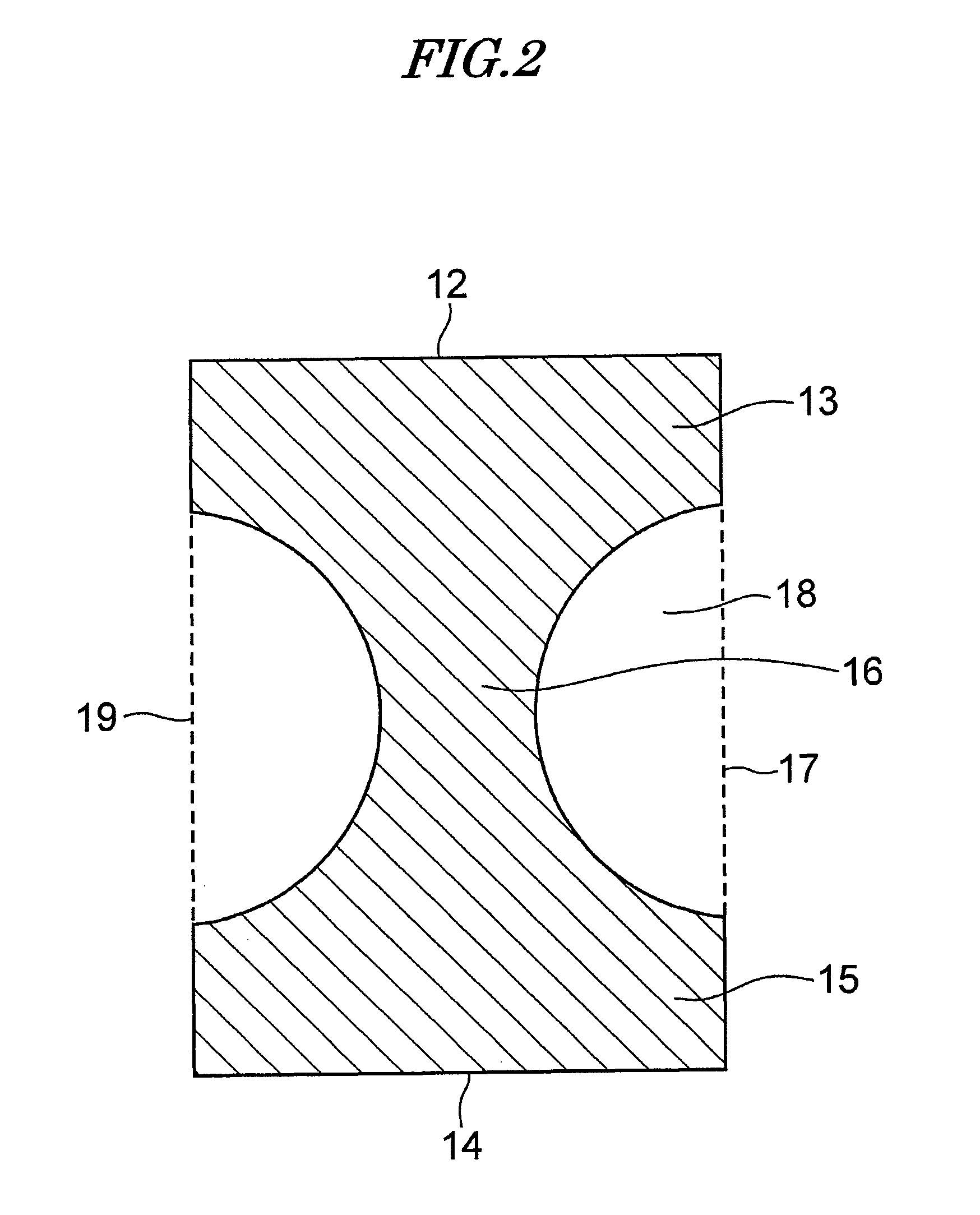
[0075]A pellicle frame with outer dimensions of 149 mm×122 mm×3.5 mm and a width of the upper edge and lower edge of 2 mm was prepared from an aluminum alloy (also called an ‘Al alloy’) (the cross-sectional shape being shown in FIG. 3 (a), and the cross-sectional area being 4.33 mm2). The cross-sectional shape was a shape obtained by removing a partial circle with a radius of 1.42 ...
example 2
[0080]A pellicle frame with outer dimensions of 149 mm×115 mm×3.0 mm and a width of the upper edge and lower edge of 2 mm was prepared from an aluminum alloy (the cross-sectional shape being shown in FIG. 3 (a), and the cross-sectional area being 3.79 mm2). The cross-sectional shape was a shape obtained by removing a partial circle with a radius of 1.042 mm having a height of 2.0 mm and a width of 0.75 mm from central parts of opposite side faces of a rectangle having a height of 3.0 mm and a width of 2.0 mm. The thickness of the upper end part and lower end part was 0.5 mm at the end parts thereof, and the width of the middle part was also 0.5 mm. When the flatness of this frame was measured from the side that was to be coated with a mask pressure-sensitive adhesive, it was found to be 10 μm. One end face of the frame was coated with the mask pressure-sensitive adhesive, and the other end face was coated with a film adhesive. Subsequently, the pellicle film previously peeled off wa...
example 3
[0082]A pellicle frame with outer dimensions of 149 mm×122 mm×3.5 mm and a width of the upper edge and lower edge of 2 mm was prepared from a magnesium alloy (also called an ‘Mg alloy’) (the cross-sectional shape being shown in FIG. 3 (a), and the cross-sectional area being 4.33 mm2)), which has the same cross-sectional shape as that of Example 1. When the flatness of this frame was measured from the side that was to be coated with a mask pressure-sensitive adhesive, it was found to be 20 μm. One end face of the frame was coated with the mask pressure-sensitive adhesive, and the other end face was coated with a film adhesive. Subsequently, the pellicle film previously peeled off was affixed to the film adhesive side of the magnesium alloy frame and the film on the outer periphery of the frame was cut, thus completing a pellicle.
[0083]The pellicle thus completed was affixed to a 142 mm square mask with a flatness of 0.25 μm using a load of 20 kgf. Subsequently, when the flatness of t...
PUM
| Property | Measurement | Unit |
|---|---|---|
| area | aaaaa | aaaaa |
| area | aaaaa | aaaaa |
| area | aaaaa | aaaaa |
Abstract
Description
Claims
Application Information
 - R&D
- Intellectual Property
- Life Sciences
- Materials
- Tech Scout
- Unparalleled Data Quality
- Higher Quality Content
- 60% Fewer Hallucinations
Browse by: Latest US Patents, China's latest patents, Technical Efficacy Thesaurus, Application Domain, Technology Topic, Popular Technical Reports.
© 2025 PatSnap. All rights reserved.Legal|Privacy policy|Modern Slavery Act Transparency Statement|Sitemap|About US| Contact US: help@patsnap.com


