Rotor bearing for a wind turbine

a technology for wind turbines and bearings, applied in the direction of bearings, roller bearings, shafts, etc., can solve the problems of over-exceeding the maximum permissible operating temperature premature failure of large roller bearings in the end, and increasing friction between roller bodies and raceways in bearing rings, etc., to achieve the effect of relatively easy compensation for processing errors

Inactive Publication Date: 2012-07-17
SCHAEFFLER TECH AG & CO KG
View PDF16 Cites 2 Cited by
  • Summary
  • Abstract
  • Description
  • Claims
  • Application Information

AI Technical Summary

Benefits of technology

[0012]Designing the large roller bearing as a two-row conical roller bearing in this case represents the preferred practical embodiment since this type of bearing fundamentally has higher load ratings and a higher power density. However, if the intention is to use large roller bearings with larger diameters, in which the power density no longer represents the critical criterion, a technically quite acceptable alternative is to be also designed in the form of a two-row inclined ball bearing. In this case, the two types of bearing, both for the inner bearing ring and for the outer bearing ring, can either be attached in a rotationally fixed manner to the machine housing or to the machine support, or else can be connected to the rotor hub of the rotor, in which case the axially asymmetric separation of the inner bearing ring of both embodiments into two ring elements is necessarily primarily to allow the large roller bearing to be installed more easily.
[0013]Independently of the previously described embodiments, a further feature of the rotor bearing according to the invention, as claimed in claim 4, is that, as a result of the asymmetric subdivision, the inner bearing ring comprises a first ring element, which has the complete internal tooth system on its inner face, and a second ring element, which is mounted on this ring element by a push fit. The asymmetric subdivision of the inner bearing ring therefore has the advantage, at the same time that the large roller bearing can be installed more easily, that the internal tooth system can be incorporated entirely in one of the ring elements, and can therefore be produced at a lower cost. In this case, it has been found to be particularly advantageous for the second ring element to completely form one of the two raceways for the roller bodies of the large roller bearing, although other asymmetric subdivisions of the inner bearing ring are also feasible.
[0016]However, more recent gearbox concepts generally provide an oblique tooth system for all the wheels in the epicyclic gearbox, since this tooth system makes it possible to choose an inclination angle which results in a considerably greater coverage level in the tooth system in comparison to a straight tooth system, thus considerably reducing vibration and noise during wind operation. Furthermore, the tooth system can be designed to have up to twice the tooth length of a straight tooth system, thus allowing considerably greater torque to be transmitted while occupying the same amount of physical space. In addition, the oblique tooth system offers the capability to compensate for external axial forces in that the inclination direction of the tooth system is designed to correspond to the direction of the externally acting axial forces.
[0017]However, by far the greatest advantages are offered by an epicyclic gearbox in which both the hollow wheel and the planet wheels as well as the sun wheel have a double-inclined or arrow tooth system. The special feature of such a double-inclined or arrow tooth system is in this case the high coverage level of the tooth system, which allows quiet, low-vibration operation of the epicyclic gearbox. The two-directional axial forces, which result from the oblique tooth systems in opposite directions, are in this case directed such that they cancel one another out, thus ensuring optimum load transmission. Furthermore, a double-inclined or arrow tooth system has the particular advantage that the axially moving bearing of the planet wheels compensates for any alignment errors between the two tooth-system areas which result on the inner bearing ring when manufacturing the tooth systems, since the planet wheels are automatically centered by the tooth-system profile.
[0020]Another suitable measure for adjusting the axial play of the large roller bearing in the form of a conical roller bearing or inclined ball bearing would also, as an alternative, be to at least provide the second ring element of the inner bearing ring with a defined width by grinding its axial side facing the first ring element. However, it would also be feasible to appropriately machine the mutually facing axial sides of both ring elements or to influence their axial size by coatings. Since processing such as this is relatively complex and costly from the manufacturing point of view, however, the use of a spacer ring for axial play adjustment has been found to be most advantageous both for cost reasons and for the reason that this also makes it possible to compensate relatively easily for any processing errors in the width of the spacer ring, by replacement by a fitting spacer ring.
[0021]In summary, the rotor bearing according to the invention therefore has the advantage over rotor bearings known from the prior art that the large rotor bearing, as before, can absorb all the forces and torques acting on the rotor while, at the same time, carrying out the function of this hollow wheel by means of the tooth system of the hollow wheel of the downstream epicyclic gearbox being integrated in the inner bearing ring. The rotor bearing according to the invention is therefore compact and weighs less, and is distinguished by a smaller number of individual parts on the large roller bearing and on the epicyclic gearbox. Furthermore, the integral nature of the inner bearing ring and hollow wheel means that the negative influences which previously occurred because of the positive excessive fit size in the push fit between the inner bearing ring and the hollow wheel on the function of the bearing point or on the tooth system in the epicyclic gearbox, are reliably precluded.

Problems solved by technology

However, rotor bearings such as these have the disadvantage that the large roller bearing and the downstream epicyclic gearbox comprise a relatively large number of individual parts and are therefore on the one hand highly costly to manufacture, while on the other hand having a high total weight, which has a highly disadvantageous effect when they are being installed in the machine housing at a height of up to 120 m. Furthermore, both the hollow wheel of the epicyclic gearbox and the inner bearing ring of the large roller bearing, which generally have an external or internal diameter of more than 2.00 m, must be manufactured extremely precisely, despite their size, in order to make it possible to reliably preclude the negative influences, which result from a positive excess fit size and from an excessively tight fit in the push connection between the inner bearing ring and the hollow wheel, on the function of the bearing point or on the tooth system of the epicyclic gearbox.
By way of example, an excessively tight fit such as this can on the one hand lead to the inner bearing ring of the large roller bearing widening slightly when it is being mounted on the hollow wheel, and in the radial play which is set in the large roller bearing being too small, thus excessively increasing the friction between the roller bodies and their raceways in the bearing rings.
This would result in the maximum permissible operating temperature of the large roller bearing being exceeded, to partial combustion of the lubricant and thus to a lack of lubrication in the large roller bearing, with the large roller bearing in the end failing prematurely.
On the other hand, it is also possible for the excessively tight fit between the inner bearing ring of the large roller bearing and the hollow wheel of the epicyclic gearbox to lead to a slight constriction of the hollow wheel, as a result of which the contact points between the internal tooth system on the hollow wheel and the tooth systems on the planet wheels of the epicyclic gearbox changing, with the result that force is no longer transmitted in a defined manner within the epicyclic gearbox, in the worst case leading to teeth breaking on one of the tooth systems.

Method used


Image

  • Rotor bearing for a wind turbine
  • Rotor bearing for a wind turbine
  • Rotor bearing for a wind turbine

Examples


first embodiment

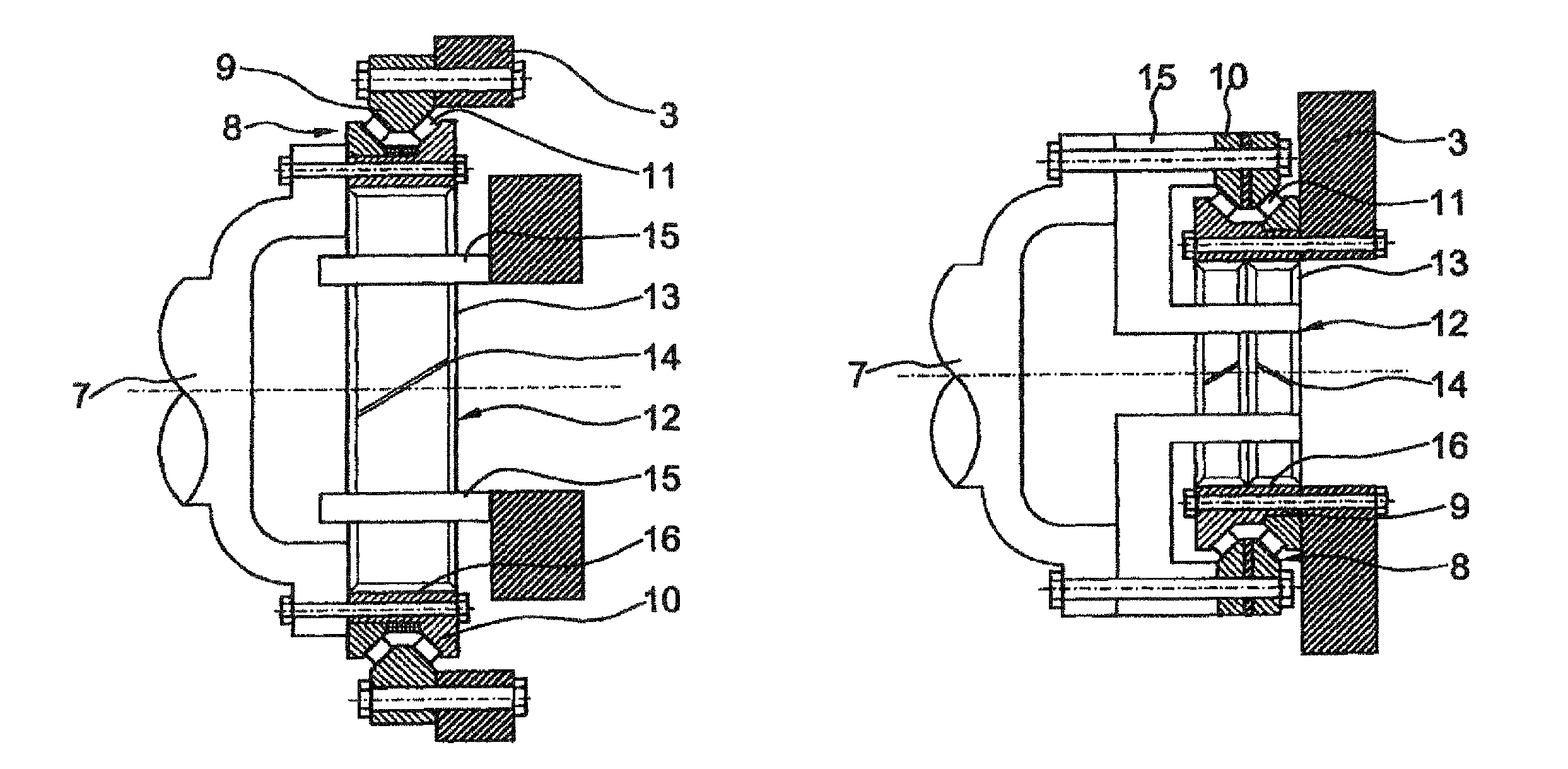
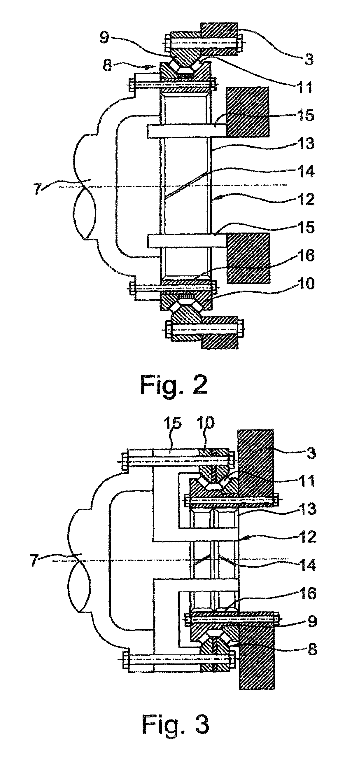
[0010]Accordingly, for the rotor bearing according to the invention, claim 2 provides that in a first embodiment the large roller bearing is preferably in the form of a conical roller bearing having two rows which are arranged alongside one another and have conical rollers as roller bodies, the inner bearing ring, which has the internal tooth system, is separated axially asymmetrically into two ring elements.

second embodiment

[0011]However, according to claim 3, it is alternatively also possible that in a second embodiment the large roller bearing is preferably formed from an inclined ball bearing having two rows which are arranged alongside one another and have bearing balls as roller bodies, the inner bearing ring, which has the internal tooth system, is separated axially asymmetrically into two ring elements.

[0012]Designing the large roller bearing as a two-row conical roller bearing in this case represents the preferred practical embodiment since this type of bearing fundamentally has higher load ratings and a higher power density. However, if the intention is to use large roller bearings with larger diameters, in which the power density no longer represents the critical criterion, a technically quite acceptable alternative is to be also designed in the form of a two-row inclined ball bearing. In this case, the two types of bearing, both for the inner bearing ring and for the outer bearing ring, can ...

third embodiment

[0028]FIG. 6 shows a partial view of a cross section through the large roller bearing of the rotor bearing according to the invention; and


PUM


Abstract

A rotor bearing for a wind turbine with a machine housing rotatably received on a tower. The housing has a generator, a wind-driven rotor with a rotor hub carrying rotor blades and a large rolling bearing carrying the rotor. The large rolling bearing has a first bearing ring, which is non-rotatably fastened on the housing and arranged coaxially to the rotor hub, and a second hearing ring, which is rotatably held on the first bearing ring and fastened to the rotor hub, and rolling elements rolling between the bearing rings. The large rolling bearing is connected to a planetary gear which is connected to the generator and has a ring gear with a peripheral internal gear, planet gears received on planet carriers and a central sun gear. The radially inner bearing ring is also the ring gear connected to the generator, its interior being configured with the peripheral internal gear.

Description

[0001]This application is a 371 of PCT / DE2008 / 001236 filed Jul. 24, 2008, which in turn claims the priority of DE 10 2007 041 508.9 filed Aug. 31, 2007, the priority of both applications is hereby claimed and both applications are incorporated by reference herein.FIELD OF THE INVENTION[0002]The invention relates to a rotor bearing for a wind energy installation as claimed in the features of patent claim 1 which form the precharacterizing clause, and it can be implemented particularly advantageously on wind energy installations having a rotor, which is mounted on a main bearing, and a downstream epicyclic gearbox.BACKGROUND TO THE INVENTION[0003]A wind energy installation such as this is already known in a generic form, for example, from WO 03 / 014 567 A1 or from U.S. Pat. No. 6,872,049 B2. The wind energy installations disclosed in these documents essentially each comprise a machine housing which is mounted on a machine tower such that it can rotate, having a generator for electricit...

Claims


Application Information

Patent Timeline
Patent Type & Authority Patents(United States)
IPC IPC(8): F03D9/00F16H57/021
CPCF03D11/0008F03D11/02F16C19/184F16C19/386F16H57/021F16H57/08F16C33/60F05B2260/40311F16C2360/31F16C2300/14Y02E10/722F16C2229/00F03D80/70F03D15/00F03D9/25F03D15/10Y02E10/72
Inventor LOESCHNER, TIMZEIDLHACK, RUDOLF
Owner SCHAEFFLER TECH AG & CO KG
Why Eureka
Try Eureka