Liquid crystal device and television receiver

a liquid crystal device and television receiver technology, applied in the field of liquid crystal devices and television receivers, can solve the problems of affecting display, increasing the capacitance between the pixel electrode and the wiring line, etc., and achieves the effect of increasing the aperture ratio, reducing the coupling capacitance, and increasing the coupling capacitance between the adjacent pixel electrodes

Inactive Publication Date: 2012-07-17
SHARP KK
View PDF9 Cites 3 Cited by
  • Summary
  • Abstract
  • Description
  • Claims
  • Application Information

AI Technical Summary

Benefits of technology

[0009]Firstly, the present liquid crystal device can achieve increase in aperture ratio, because adjacent pixel electrodes are extended so that the outer edges thereof overlap with the capacitor line.
[0010]The second is that the present construction allows for reduction in the coupling capacitance between adjacent pixel electrodes. In the construction of the present invention where the outer edges of adjacent pixel electrodes are arranged close to each other so as to overlap with the capacitor line, the coupling capacitance between the adjacent pixel electrodes is considerable high, which can affect display provided by the present liquid crystal device. In view of this, according to the present invention, the part of the capacitor line located below the conductive film is divided into a portion overlapped with the first conductive film of the conductive film and a portion overlapped with the second conductive film of the conductive film. Thereby, the coupling capacitance between the adjacent pixel electrodes can be reduced, without reducing the aperture ratio.

Problems solved by technology

However, the coupling capacitance between the pixel electrode and the wiring lines is also increased, which may affect the display.

Method used


Image

  • Liquid crystal device and television receiver
  • Liquid crystal device and television receiver
  • Liquid crystal device and television receiver

Examples


Embodiment Construction

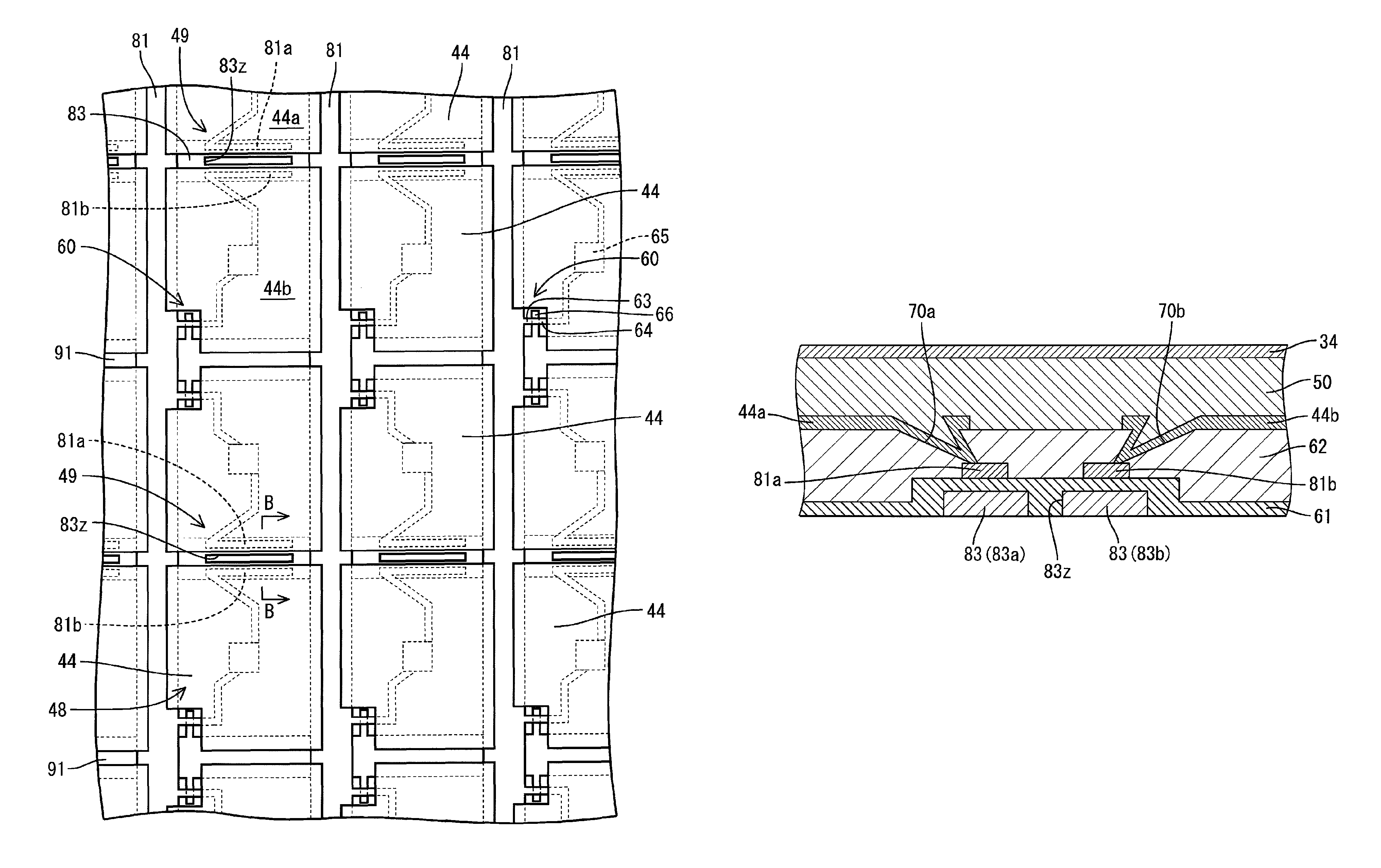
[0023]Hereinafter, an embodiment of a liquid crystal device and a television receiver according to the present invention will be explained with reference to the drawings.

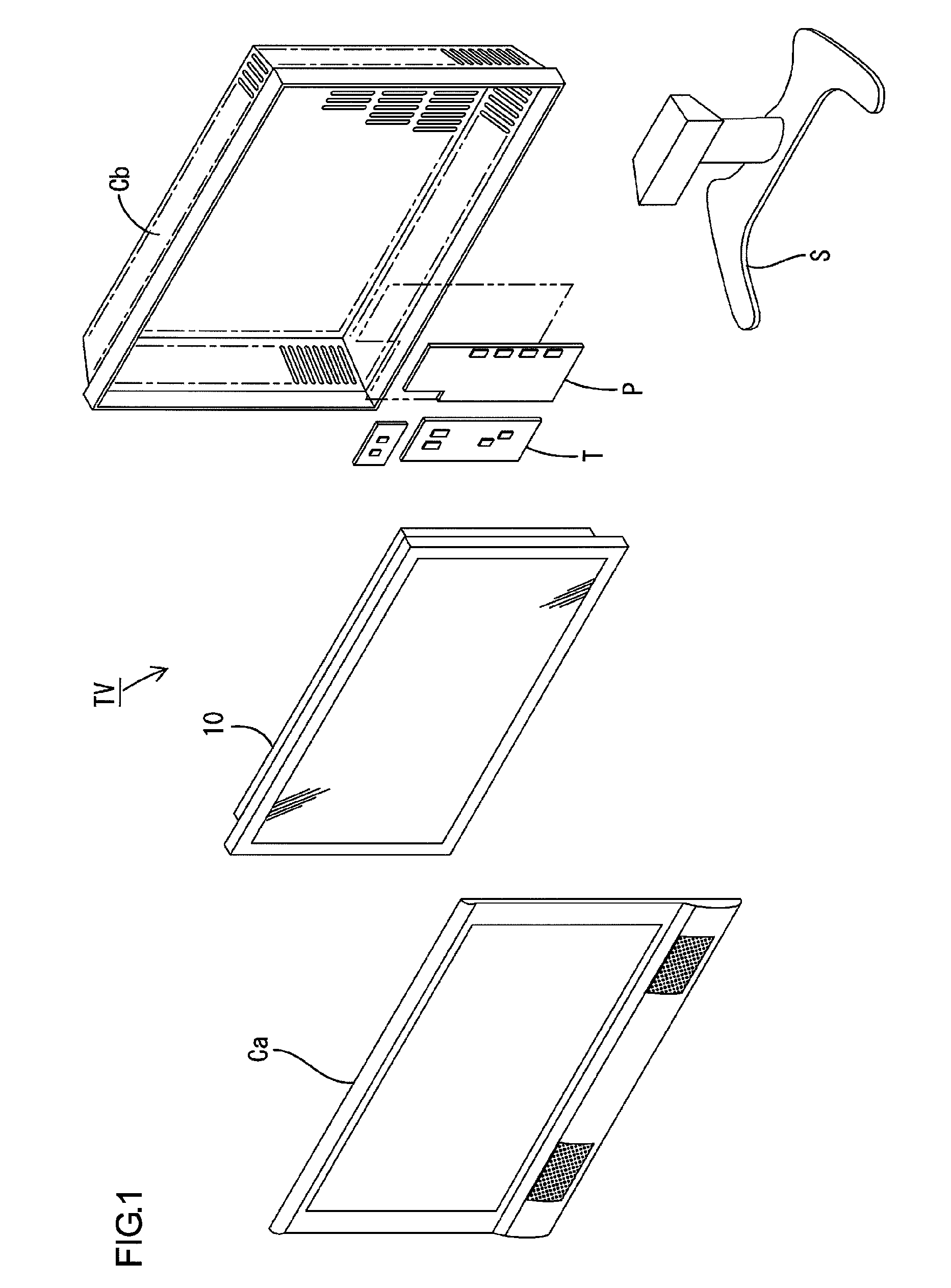
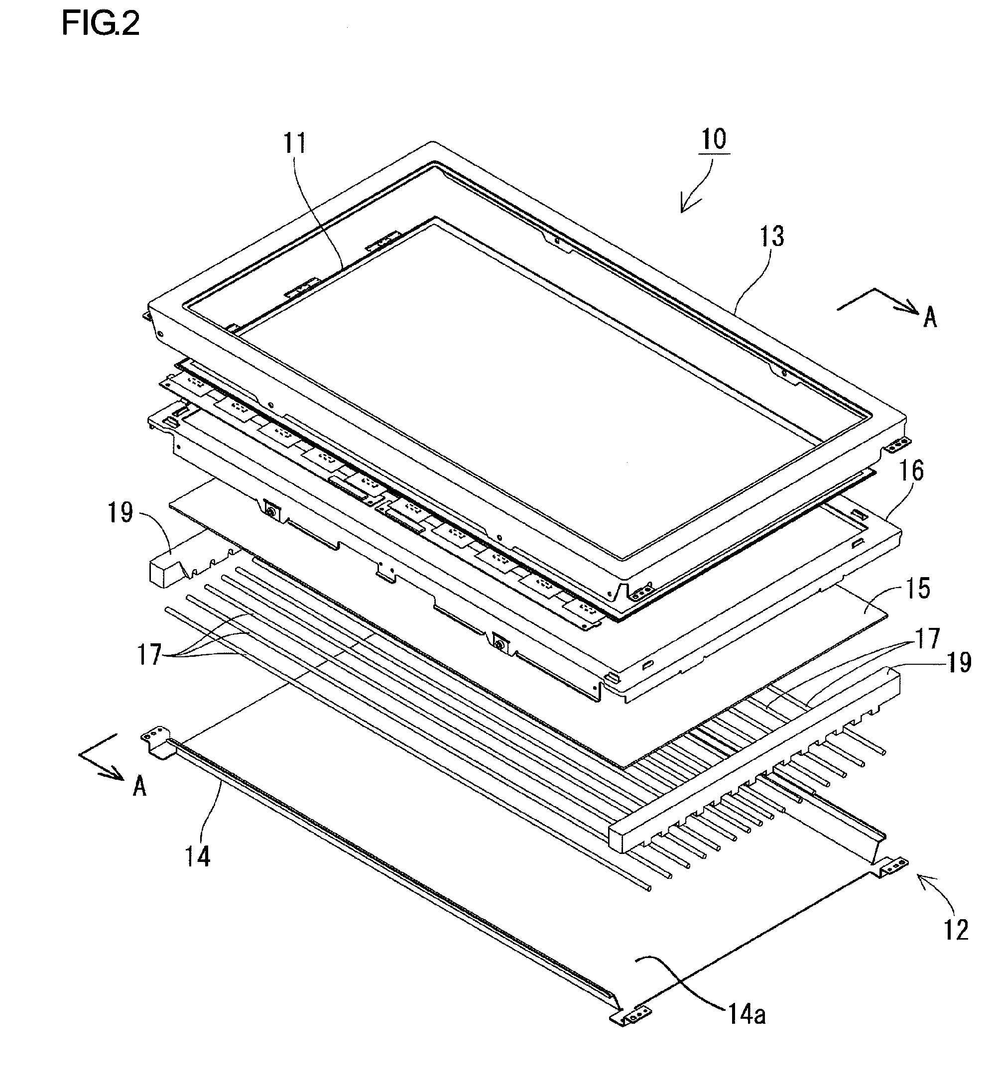
[0024]FIG. 1 is an exploded perspective view showing the general construction of the television receiver TV according to the present embodiment. FIG. 2 is an exploded perspective view showing the general construction of the liquid crystal display device (liquid crystal device) 10 included in the television receiver TV. FIG. 3 is a sectional view showing the cross-sectional configuration of FIG. 2 along the line A-A.

[0025]Referring to FIG. 1, the television receiver TV according to the present embodiment includes the liquid crystal display device (liquid crystal device) 10, and front and back cabinets Ca and Cb capable of holding the liquid crystal display device 10 therebetween. Further included are a power source P, a tuner T and a stand S. The liquid crystal display device 10 forms a horizontally-elongated rectang...


PUM

PropertyMeasurementUnit
distanceaaaaaaaaaa
distanceaaaaaaaaaa
thicknessaaaaaaaaaa

Abstract

A liquid crystal device 10 of the present invention includes conductive films 81a, 81b for storage capacitors, i.e., a first conductive film 81a and a second conductive film 81b, which are connected to two adjacent pixel electrodes 44a, 44b, respectively, via contact sections 70a, 70b formed through a second insulating film 62. The part of a storage capacitor 83 located below the conductive films 81a, 81b is divided into a first capacitor line 83a arranged below the first conductive film 81a and a second capacitor line 83b arranged below the second conductive film 81b.

Description

TECHNICAL FIELD[0001]The present invention relates to a liquid crystal device and a television receiver having the same.BACKGROUND ART[0002]A liquid crystal device is known, which has a construction that includes a pair of substrates and a liquid crystal layer arranged therebetween. One of the substrates is provided as an active matrix substrate that includes pixel electrodes. The active matrix substrate has a construction, in which gate wiring lines and signal lines are arranged on a transparent substrate so as to form a grid pattern. Switching elements such as TFTs are provided at crossover sections where the gate wiring lines and the signal lines intersect each other. At each area surrounded by the gate wiring lines and the signal lines, a pixel electrode is arranged to form a pixel as the smallest unit of an image to be displayed.[0003]In order to improve quality in display, or specifically, to enhance the brightness, the liquid crystal device is expected to have high aperture r...

Claims


Application Information

Patent Timeline
Patent Type & Authority Patents(United States)
IPC IPC(8): G02F1/1368G02F1/133G02F1/1343
CPCG02F1/136213G09G3/3614G09G2300/0426G09G2300/0465
Inventor SUGISAKA, AKANESHIMOSHIKIRYOH, FUMIKAZU
Owner SHARP KK
Why Eureka
Try Eureka