Method of monitoring deterioration of lubricating oil and device therefore

a technology of lubricating oil and monitoring device, which is applied in the direction of resistance/reactance/impedence, voltage-current phase angle, instruments, etc., can solve the problem of difficult to say that the oil change has been done at the proper time, the viscosity and purity decrease, and the need for considerable time for chemical analysis. problems, to achieve the effect of stable measurement of the permittivity of oil, and the ability to avoid unnecessary oil chang

Inactive Publication Date: 2012-07-17
MITSUBISHI HEAVY IND LTD
View PDF20 Cites 6 Cited by
  • Summary
  • Abstract
  • Description
  • Claims
  • Application Information

AI Technical Summary

Benefits of technology

[0013]The present invention was made in light of the problems of the prior art mentioned above, and the object of the invention is to provide a method of monitoring deterioration of lubricating oil and a device therefore capable of judging deterioration of oil with high accuracy suppressing measurement errors due to mixing of foreign matted in the oil and variation of temperature of the oil to the minimum.
[0016]TBN (total base number) is used as an indicator of acid neutralizing capacity and cleanliness level of oil. TBN decreases as oil deteriorates. There is a correlation between relative permittivity and TBN of oil that relative permittivity of oil increases as TBN of oil decreases, i.e. as oil deteriorates. Therefore, by degree of deterioration of oil can be detected easily and accurately from correlation obtained beforehand between permittivity and TBN of concerned lubricating oil.
[0022]By this, foreign matter such as soot adhered to the electrodes is removed and stable measurement of permittivity of oil can be performed.
[0025]By attaching the high permittivity member to at least one of the electrodes to increase permittivity detected by the condenser constituted by the pair of electrodes, the high permittivity member, and the oil between them, the detected permittivity is increased. Therefore, even when it is difficult or impossible to detect permittivity of oil accurately, permittivity increased by attaching high permittivity member to the electrode can be detected and by subtracting offset value, i.e. value of permittivity increased due to the high permittivity member from the detected permittivity, permittivity of the oil can be obtained. Therefore, relative permittivity of oil can be detected with high accuracy.
[0030]As has been describes heretofore, according to the invention, deterioration of lubricating oil can be detected in real time without stopping operation of engines. Therefore, appropriate timing for changing oil can be grasped and unnecessary changing of oil can be evaded.

Problems solved by technology

The lubricating oil is exposed at high temperature and experiences mechanical stress in the gas engine and deteriorates, that is, viscosity and purity decreases.
However, considerable time is needed to obtain chemical analysis after sampling the lubricating oil, and it is hard to say changing oil has been done at proper timing.
However, with the art disclosed in the Document 1, degree of oil deterioration is judged based on decrease in electric resistance of the oil, which is susceptible to mixing of foreign matter such as carbon in the oil.
With the art disclosed in the Document 1, also the electric capacitance is influenced by temperature of the oil and foreign matter mixed in the oil, resulting in increased measurement deviation.
There are other methods of detecting deterioration of oil, for example, by measuring change in viscosity, change in light transmission, or change in pH of the oil, however, these measurements are also influenced by temperature of the oil or foreign matter in the oil, and proper judgment of degree of deterioration of oil has been not easy.

Method used


Image

  • Method of monitoring deterioration of lubricating oil and device therefore
  • Method of monitoring deterioration of lubricating oil and device therefore
  • Method of monitoring deterioration of lubricating oil and device therefore

Examples


Embodiment Construction

[0042]Embodiments of the present invention will now be detailed with reference to the accompanying drawings. It is intended, however, that unless particularly specified, dimensions, materials, relative positions and so forth of the constituent parts in the embodiments shall be interpreted as illustrative only not as limitative of the scope of the present invention.

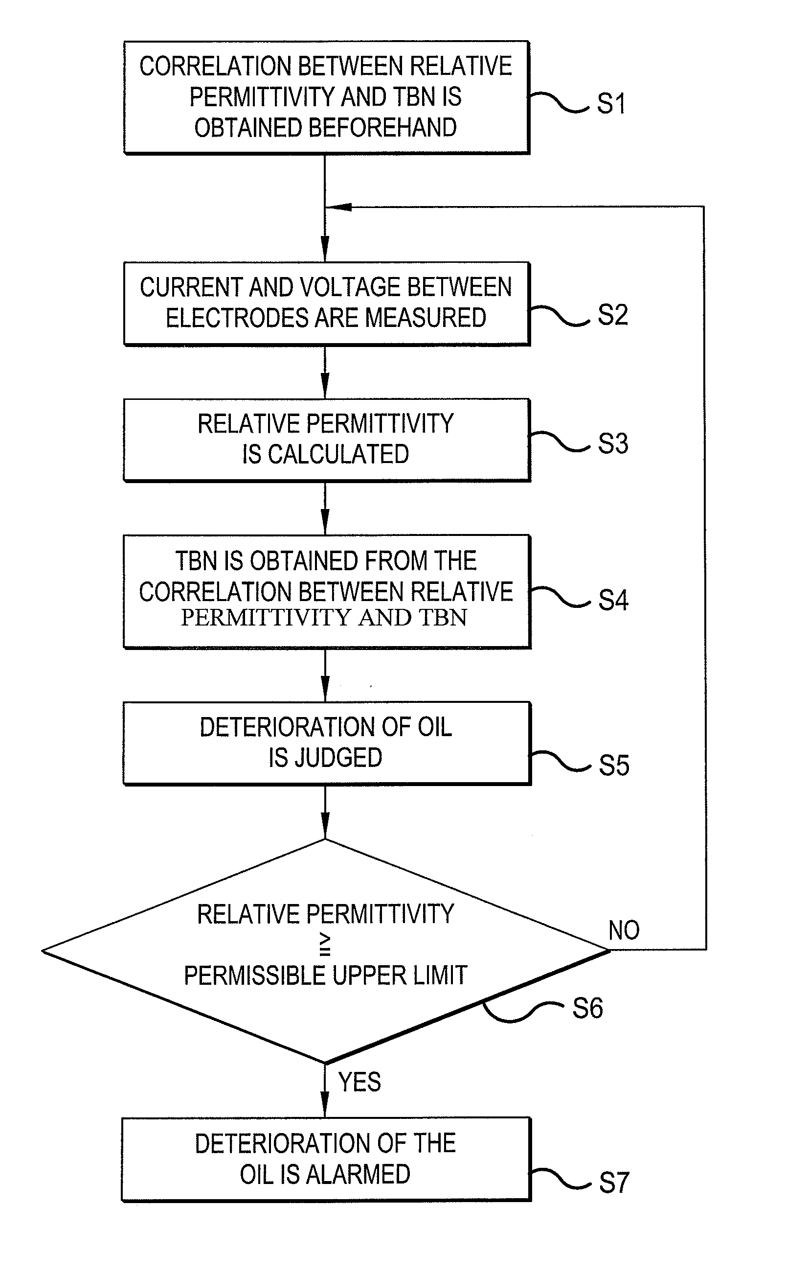
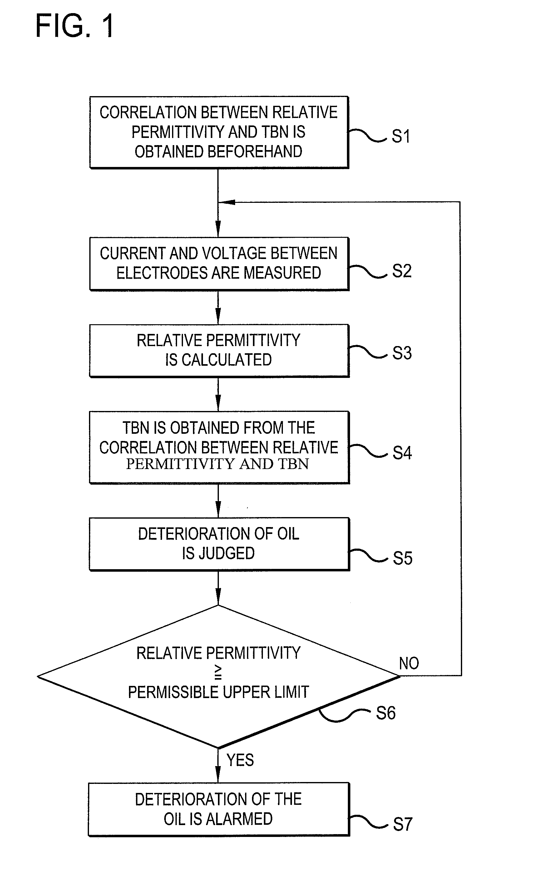
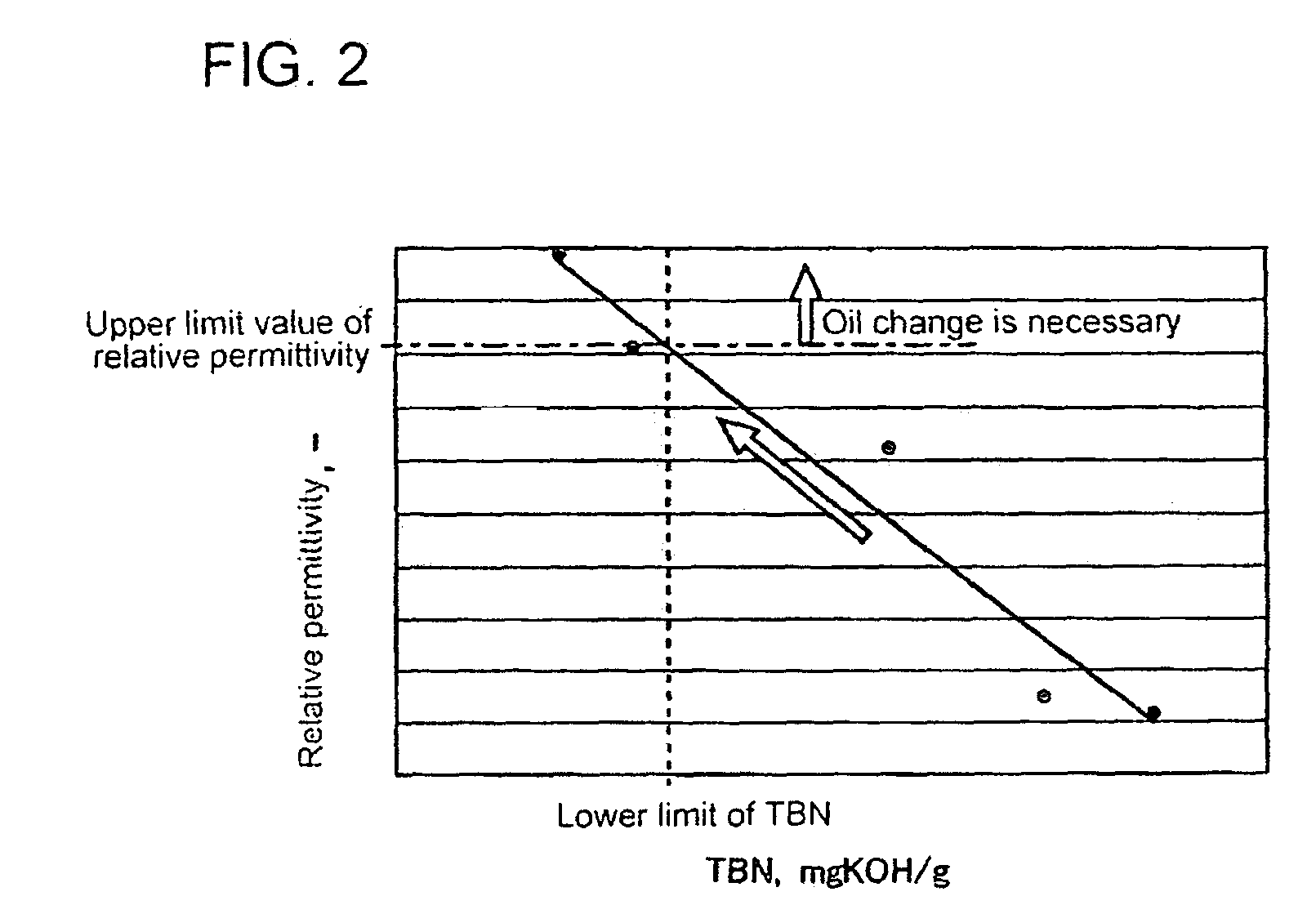
[0043]FIGS. 1 to 6 are drawings to explain the method of monitoring deterioration of lubricating oil and the device therefore of an embodiment according to the invention, FIGS. 7 to 11 are drawing to explain modifications of embodiment.

[0044]In a gas engine 26 for driving an electric generator 27, lubricating oil accumulated in an oil tank is supplied through oil path via an oil filter and oil cooler to pistons, cylinders, bearings, etc. for lubrication and cooling of them and returned to the oil tank to be again supplied to the parts to be lubricated. The device of the embodiment of the invention is for detecting oil dete...


PUM


Abstract

A method of monitoring deterioration of lubricating oil and a device therefore capable of judging deterioration of the oil with high accuracy suppressing measurement error due to mixing of foreign matter in the oil. Correlation between relative permittivity and TBN (total base number) of the lubricating oil is obtained beforehand (step S1), electric current and voltage are measured (step S2) when high-frequency voltage is applied between a pair of electrodes located in an oil path in a gas engine, permittivity of the oil is detected (step S3) based on the measurement of current and voltage, TBN of the oil is obtained (step S4) from the correlation between relative permittivity and TBN, and deterioration of the oil is judged by the obtained value of TBN.

Description

BACKGROUND OF THE INVENTION[0001]1. Field of the Invention[0002]The present invention relates to a method and device for detecting deterioration of lubricating oil circulating in a gas engine for driving an electric generator to lubricate sliding surfaces in the engine and monitoring the lubricating oil deterioration, specifically to those with which deterioration of oil can be detected in real time.[0003]2. Description of the Related Art[0004]Gas engines for driving electric generators have an oil tank and oil supply device to supply lubricating oil to rotating parts and sliding parts in order to secure smooth movement of the parts preventing abrasion of them. The lubricating oil accumulated in the oil tank is supplied through oil path via an oil filter and oil cooler to pistons, cylinders, bearings, etc. for lubrication and cooling of them and returned to the oil tank to be again supplied to the parts to be lubricated.[0005]The lubricating oil is exposed at high temperature and ex...

Claims


Application Information

Patent Timeline
Patent Type & Authority Patents(United States)
IPC IPC(8): G01R27/00
CPCG01N27/221G01N33/2876
Inventor AKIYAMA, YOYANO, AKIHIKOKAGA, JUNICHI
Owner MITSUBISHI HEAVY IND LTD
Why Eureka
Try Eureka