Charge intercooler for a motor vehicle

a technology for intercoolers and motor vehicles, which is applied in the direction of indirect heat exchangers, machines/engines, lighting and heating apparatus, etc., can solve the problem of less cooling of emerging charge air, and achieve the effect of reducing the cooling of charge air

Active Publication Date: 2012-07-24
BEHR GMBH & CO KG
View PDF70 Cites 14 Cited by
  • Summary
  • Abstract
  • Description
  • Claims
  • Application Information

AI Technical Summary

Benefits of technology

[0005]According to the invention, it is provided that, for the reduced cooling, a certain number of tubes of the charge intercooler is shut off, i.e. the charge air is prevented from flowing through these tubes. Accordingly, for example, only 10 percent to 30 percent of the tubes have charge air flowing through them, which results in a lesser cooling of the emerging charge air. The advantage achieved by this is that—even in the—case of unfavorable outside conditions, for example low outside temperatures—an increased exhaust gas temperature required for filter regeneration or a particulate burn-off is obtained.
[0008]According to an advantageous refinement of the invention, the flap is designed as a preferably rectangular flap with a lateral pivot axis, said flap being arranged in the immediate region of the tube ends and therefore covering or closing some of the tube ends. The flap can be arranged and fastened in the air box in a relatively simple manner. When the flap is open, i.e. the tubes are not closed, the bearing of the flap against the wall of the charge air box does not cause any additional drop in pressure for the standard charge air cooling in which all of the tubes have charge air flowing through them.
[0010]According to a further advantageous refinement of the invention, the air box is divided by a transverse partition into two chambers, with each chamber being assigned some of the total number of charge air tubes. The two chambers are preferably brought together in a funnel-shaped passage (bottleneck) where the shut-off member is arranged. The latter closes one of the two chambers, preferably the chamber with a higher number of tubes, as a result of which the flow charge air through these tubes is prevented. The advantage of this solution is that the shut-off member can be designed to be smaller than the cross-sectional area of the tubes that is to be covered, as a result of which the actuating forces for displacing the shut-off member are also lower. This constricted passage cross section is preferably of round design and the cross section of the flap is correspondingly matched.
[0012]According to an embodiment, the shut-off member is designed as a half-round flap with a lateral or central pivot axis. Under some circumstances, it is possible for the flap to be placed against a wall, in particular a partition, during opening. In this case, a reduction in the flow resistance caused by the flap is possible.
[0013]According to a further embodiment, the shut-off member has sections for covering individual tubes, so that these tubes can be blocked. In this case, the covering sections are preferably mounted in a manner such that they can be displaced and / or rotated together. In particular, the covering sections can be displaced between a position covering the tube ends and a position offset with respect to the tube axes. In another example, the covering sections are mounted on a common axis, with the axis extending in the longitudinal direction of a tube row. It is likewise possible to rotate and to slide individual covering sections at the same time out of the mouth region of individual tubes.
[0015]The charge intercooler has air flowing through it in a U-shaped manner, i.e. twice and, on one side, has a charge air box with an entry and exit opening and a partition and, on the other side, a deflecting box. A shut-off member preferably a round pivoting flap, is arranged in the partition. The advantage of a reduced charge air cooling when the flap is open is therefore likewise achieved because a considerable portion of the charge air flowing in passes directly, i.e. without cooling, into the outlet. The advantage of this solution is above all the fact that the shut-off member in the partition is constructively relative simple to control and is therefore associated only with a little additional outlay.

Problems solved by technology

Accordingly, for example, only 10 percent to 30 percent of the tubes have charge air flowing through them, which results in a lesser cooling of the emerging charge air.

Method used


Image

  • Charge intercooler for a motor vehicle
  • Charge intercooler for a motor vehicle
  • Charge intercooler for a motor vehicle

Examples


Embodiment Construction

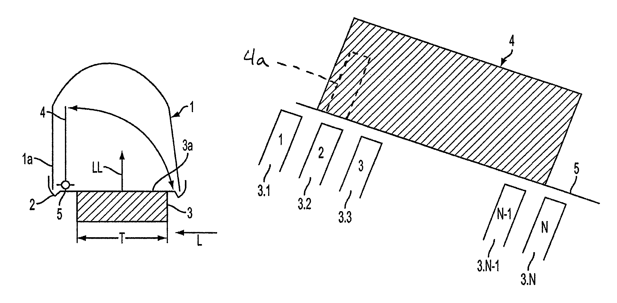
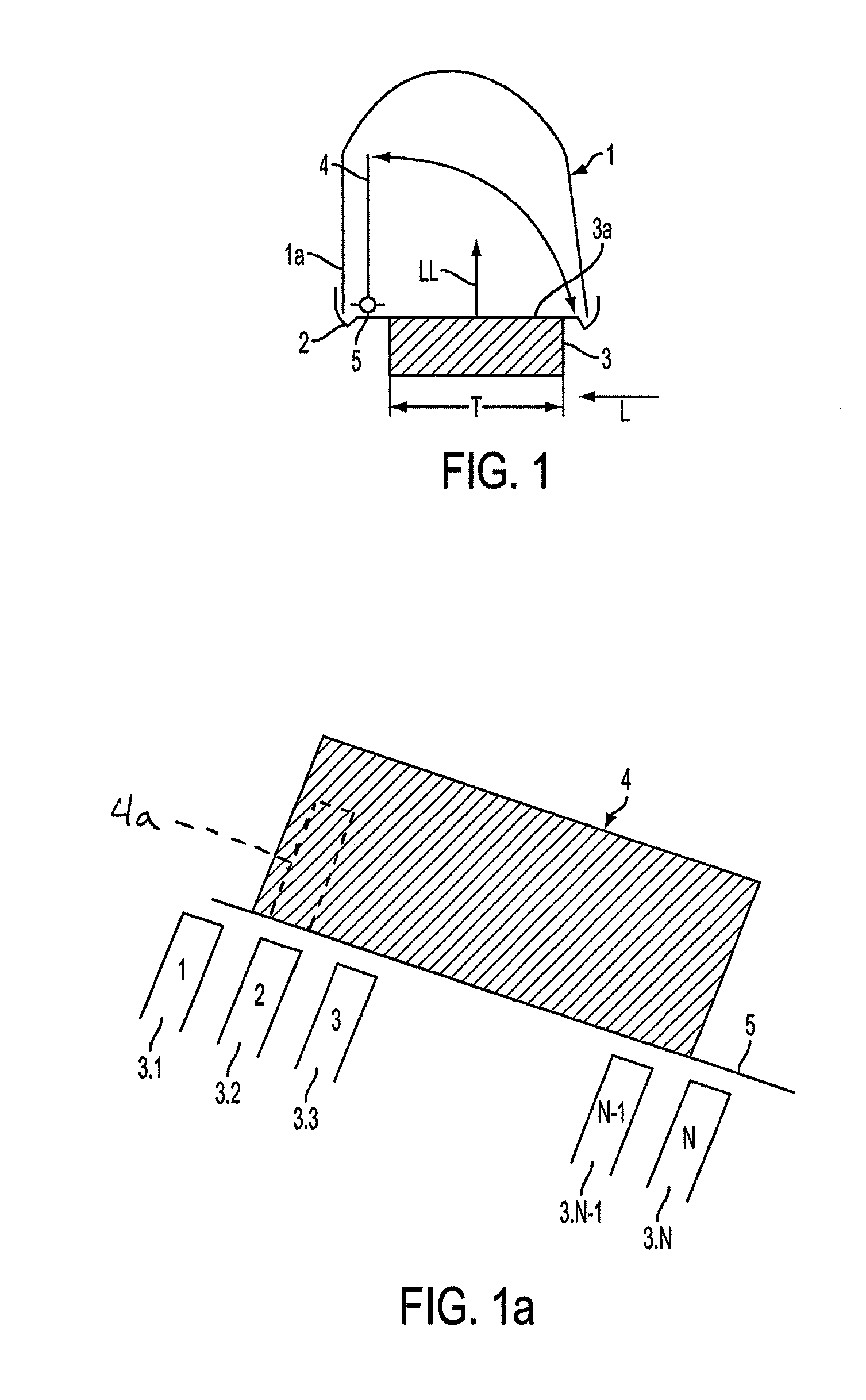
[0028]FIG. 1 shows, in a diagrammatic illustration, an air box 1 on the exit side of a charge intercooler (not entirely illustrated) which has a further air box on the entry side (not illustrated). The air box 1, on which an air outlet (not illustrated) is arranged, is placed onto a tube plate 2 and is connected thereto. The tube plate 2 is preferably produced from an aluminum material and has—perpendicularly to the plane of projection—a series of rims (not illustrated specifically) into which tubes 3 are inserted by their tube ends 3a and are soldered. The air box 1 can be produced from a plastic or aluminum material. Accordingly, the connection to the metallic tube plate 2 is a mechanical flared connection or a connection with a cohesive material joint, for example a soldered connection. The tubes 3 have a rectangular cross section, the long side of which with the depth T lies parallel to the plane of projection. Arranged between the tubes 3 are corrugated fins (not illustrated) w...


PUM


Abstract

A charge intercooler for a motor vehicle includes a heat transfer block with tubes through which charge air flows, airboxes connected to the tubes that form a charge air inlet and a charge air outlet, and a movable body mounted in one of the airboxes for selectively blocking at least some of the tubes.

Description

FIELD OF THE INVENTION[0001]The invention relates to a charge intercooler for a motor vehicle.BACKGROUND OF THE INVENTION[0002]Charge intercoolers for motor vehicles are known; they serve to cool the combustion air compressed by a compressor or turbocharger in order to obtain a better filling of the cylinders, i.e. a better charging efficiency. For motor vehicles, use is generally made of air-cooled charge intercoolers, as have been disclosed, for example, by DE-A 198 57 435 or DE-A 199 62 861 of the applicant. The charge intercooler generally has a heat exchanger unit or a “network” which comprises tubes, generally flat or rectangular tubes, between which corrugated fins are arranged to enlarge the heat exchange surface. The tubes are held by their tube ends in tube plates. Tubes, fins and tube plates are composed of aluminum materials and are soldered to one another. “Air boxes” which act as distributors or header boxes for the charge air are placed onto the tube plates. These air...

Claims


Application Information

Patent Timeline
Patent Type & Authority Patents(United States)
IPC IPC(8): F01N5/02F02M25/07F28F27/02F02B33/00F02B29/04F02D9/10F02D9/16F28F9/02
CPCF02B29/0418F02B29/0456F02B29/0475F28F9/02F28F27/02F02D9/103F02D9/16F28D2021/0082Y02T10/146Y02T10/12
Inventor HENDRIX, DANIEL
Owner BEHR GMBH & CO KG
Why Eureka
Try Eureka