Cab suspension

a technology for suspension and cabs, applied in the field of cab suspension, can solve the problems of limiting the transport speed of these windrowers, and achieve the effects of avoiding complex control systems, inexpensive links, and effective support of operators

Active Publication Date: 2012-07-24
MACDON INDS
View PDF15 Cites 41 Cited by
  • Summary
  • Abstract
  • Description
  • Claims
  • Application Information

AI Technical Summary

Benefits of technology

[0029]This arrangement preferably has the effect that the first link and the second link are arranged such that steering and ground speed are substantially unaffected when the cab moves on the suspension.
[0035]Preferably there is provided a third link which is parallel to either the first link or to the second link, the third link being substantially horizontal and arranged such that the third link prevents movement of the base relative to the frame in a direction longitudinal of the third link.
[0036]Preferably the first, second and third links prevent rotation or twisting of the cab around a vertical center line.
[0044]This arrangement of speed / steering links and the stabilizing links ensures that the steering and ground speed are affected only slightly when the cab floats up and down. This allows the cab suspension to have the four point suspension, which is superior to two point suspension systems typically used for such cabs.
[0048]Preferably the third link extends in the side to side direction and has one end thereof substantially at a center line of the base and the other end at the side of the cab. The link can be arranged with the outer end fastened to the base and the inner end to the frame or vice versa as this has no effect. The location of the inner end at approximately the mid-line of the cab provides sufficient strength without interfering with the links in the fore and aft directions.
[0049]The arrangement in which the center of the base of the cab is constrained to move substantially vertically while allowing pitch and roll movements of the cab is advantageous in that it effectively supports the operator against tiring movements and also it allows the control systems of the cab which communicate though the base to operate the drive and steering without the danger of a rhythmic cycle of movement or “hunting” being generated. The arrangement uses simple commercially available spring and shock absorbers with inexpensive links and avoids the use of complex control systems using sensors responsive to the movement.

Problems solved by technology

There has been a limit to the transport speed of these windrowers due to instability at high speed with the drive wheels ahead of the castor wheels (cab forward).

Method used


Image

  • Cab suspension
  • Cab suspension
  • Cab suspension

Examples


Embodiment Construction

[0065]The following description is taken from previously mentioned published US Application 2009 / 0242219 for complete disclosure of the construction herein and relates to FIGS. 1 to 8 of that application.

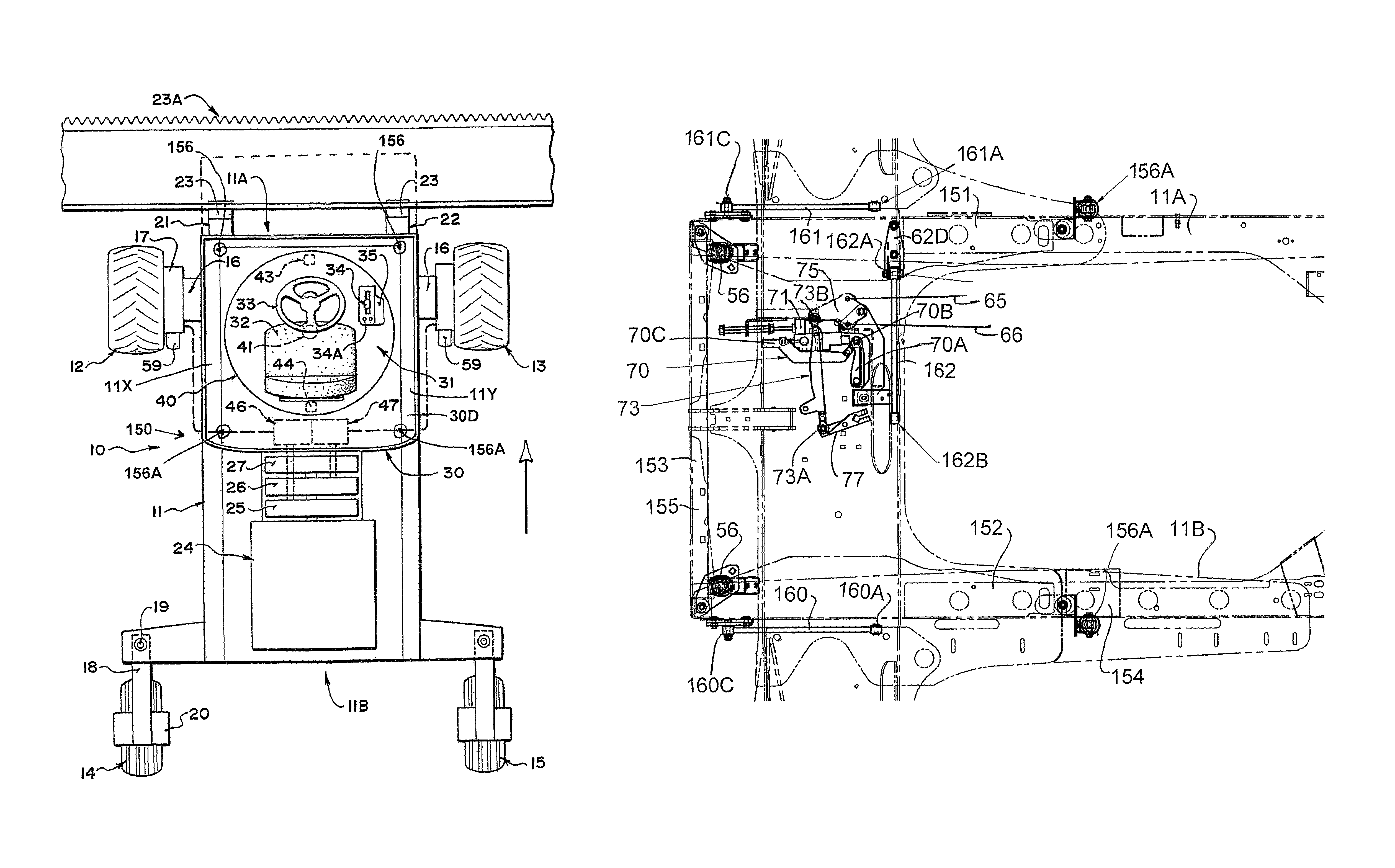
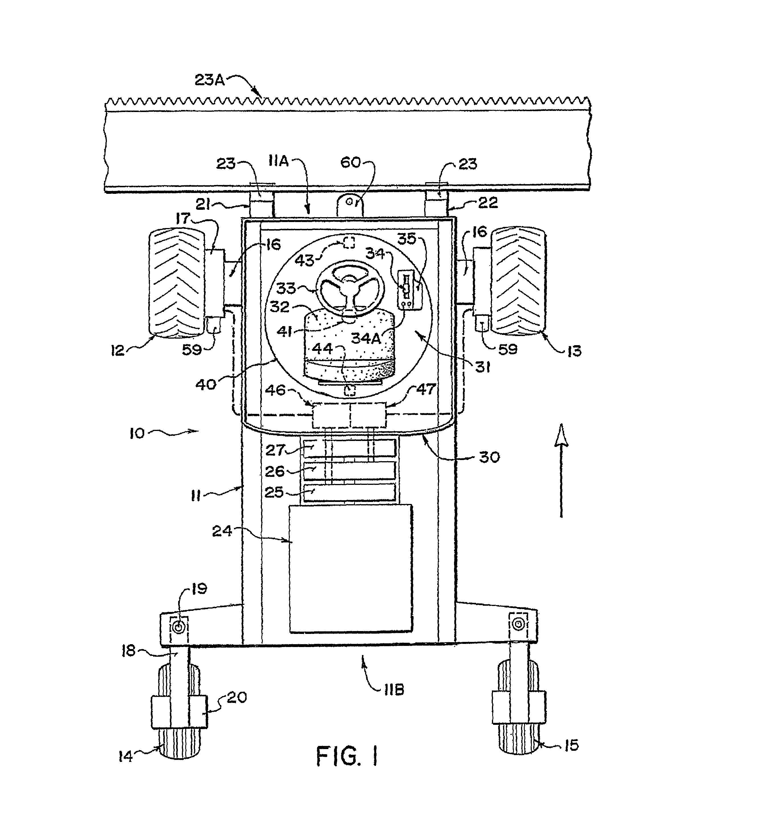
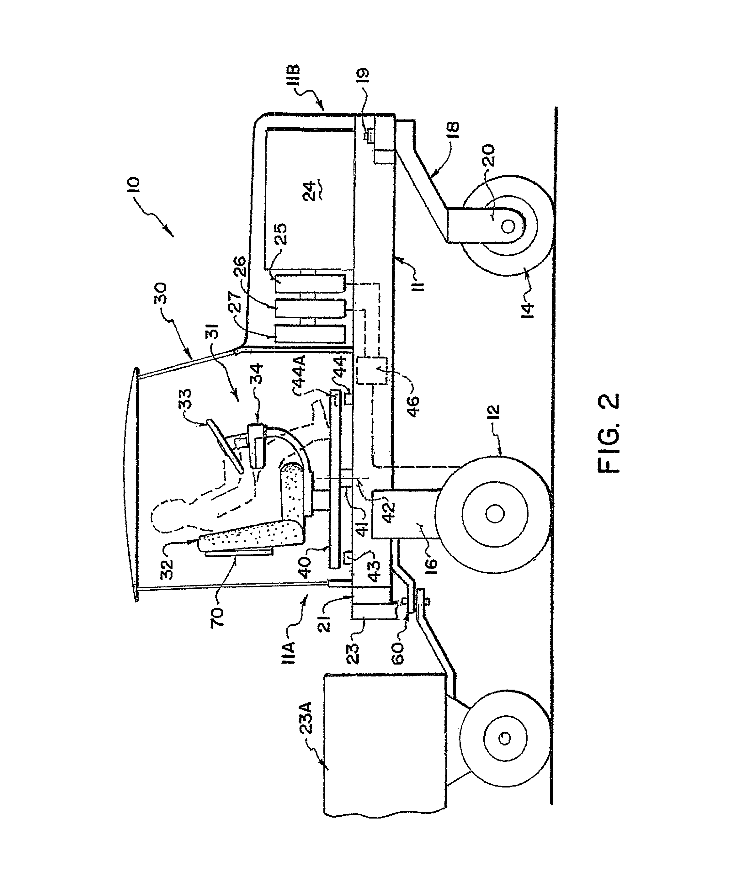
[0066]A swather tractor generally indicated at 10 includes a frame 11 which is carried on a first pair of driven ground wheels 12 and 13 and on a second pair of non-driven castor wheels 14 and 15. The driven wheels 12 and 13 are mounted on suitable supports 16 which support the ground wheels from the frame 11. The driven ground wheels 12 and 13 are each driven by a hydraulic motor 17 carried on the support 16 which receives hydraulic fluid under pressure from a supply line and drives the ground wheel at a rate of rotation dependant upon the rate of flow of the hydraulic fluid.

[0067]The wheels 14 and 15 are mounted on conventional castors 18 which swivel about a castor pin 19. The ground wheels 14 and 15 are non driven and are simply mounted in a supporting bracket 20 which can pivot...


PUM


Abstract

A suspension for a cab base on the frame of a swather tractor includes four dampened springs at the four corners with three links each pivoted on one end of the frame and the other end on the base. The links include two parallel links in the fore and aft direction parallel to the mechanical speed control link arm and one side to side link which constrain movement of the base against fore and aft movement and side to side movement parallel to the mechanical steering control link arm. This arrangement restricts movement of the base while allowing roll and pitch movements of the cab structure with the links arranged such that steering and ground speed are substantially unaffected when the cab moves on the suspension.

Description

[0001]This application claims priority under 35 USC 119 of Provisional application Ser. No. 12 / 616,989 filed Nov. 12, 2009.[0002]This invention relates to a cab suspension system for a hydraulically driven and steered swather tractor.BACKGROUND OF THE INVENTION[0003]Hydrostatically steered tractors have been available for many years and their application to windrowers has been significant. There has been a limit to the transport speed of these windrowers due to instability at high speed with the drive wheels ahead of the castor wheels (cab forward). Higher speeds on the road allow the user to cover large distances without the use of trailers and tow vehicles.[0004]In U.S. Pat. No. 7,306,062 issued Dec. 11, 2007 by inventor Dunn and assigned to the present assignee is shown a tractor of this type in which the machine travels in transport mode with the castor wheels leading the drive wheels (engine forward), and in this position the machine is much more stable and higher speeds are po...

Claims


Application Information

Patent Timeline
Patent Type & Authority Patents(United States)
IPC IPC(8): B62D33/08
CPCB62D11/001B62D11/006B60G99/002B62D33/0608B60G2300/08B60G2204/162
Inventor DUNN, JAMES THOMAS
Owner MACDON INDS
Why Eureka
Try Eureka