Refiner

a technology of refiner and refractory, which is applied in the field of refiner, can solve the problems of preventing the effective utilization of the refiner, unhomogeneous pulp quality, and loading capacity of the refiner, and achieves the effect of reducing the cost of refinery

Active Publication Date: 2012-07-24
VALMET TECH INC
View PDF9 Cites 7 Cited by
  • Summary
  • Abstract
  • Description
  • Claims
  • Application Information

AI Technical Summary

Benefits of technology

[0009]An object of the invention is a novel refiner providing improved pulp quality.
[0010]The refiner of the invention is characterized in that the refining surface of the conical portion of the stator comprises at least an outer zone arranged at the second end of the conical portion having greater diameter and an inner zone arranged relative to the outer zone on the side of the first end of the conical portion having smaller diameter, the length of the outer zone being half of the total length between the first end and the second end of the conical portion of the stator and that a portion of the length of the blade bars in the outer zone of the conical portion of the stator are arranged relative to the rotation direction of the rotor such that they have a retentive effect on the material to be refined and that this portion of the length of the blade bars in the outer zone of the conical portion of the stator corresponds to at least 10% of the total length between the first end and the second end of the conical portion of the stator.
[0011]A blade segment of the invention is characterized in that the blade segment comprises at least an outer zone arrangeable at the second end of the conical portion of the stator having greater diameter and an inner zone arrangeable relative to the outer zone on the side of the first end of the conical portion of the stator having smaller diameter, the length of the outer zone being half of the total length of the blade segment and that a portion of the length of the blade bars in the outer zone of the blade segment are arrangeable relative to the rotation direction of the rotor such that they have a retentive effect on the material to be refined and that this portion of the length of the blade bars in the outer zone of the blade segment corresponds to at least 10% of the total length of the blade segment.

Problems solved by technology

However, the present use of refiners promotes the rotation of the rotor only in one direction due to the energy consumption and blade set lifetime reasons.
In result of this the V-shaped blade bar and blade groove form in the refining surface of the stator is problematic, because one half of the refining surface of the stator feeds the material to be refined out of the blade gap and the other half of the refining surface of the stator prevents the material to be refined moving out of the refiner, what leads to the unhomogeneous pulp quality.
The variation of the intersecting angle of the V-shaped blade bars of the stator decreases the loading capacity of the refiner, thus preventing the effective utilization of the refiner.

Method used


Image

  • Refiner
  • Refiner
  • Refiner

Examples


Embodiment Construction

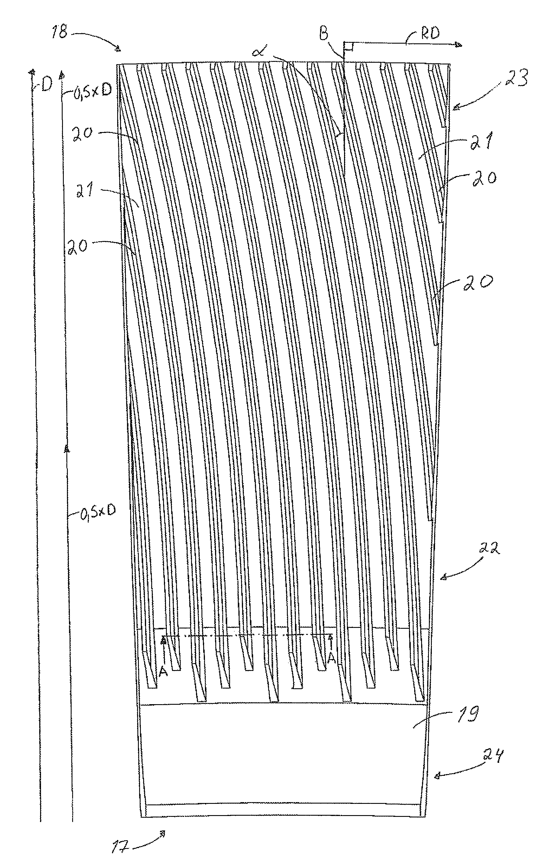
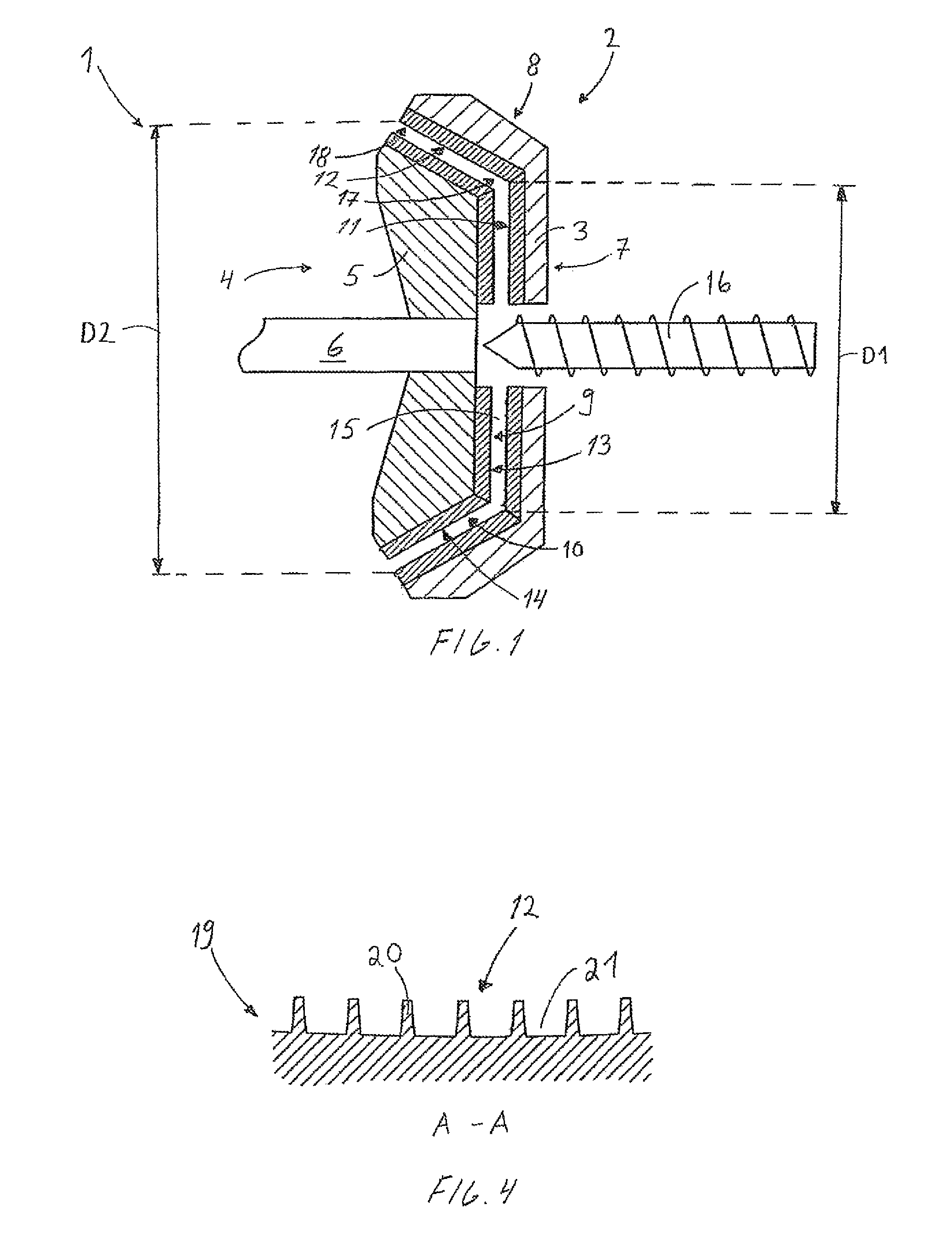
[0024]FIG. 1 is a schematic view of a refiner 1 for refining fibrous material. The refiner 1 is provided with a fixed stator 2, supported to a frame of the refiner 1 not shown in FIG. 1. The stator 2 comprises a frame part 3 of the stator 2 and a refining surface consisting of blade bars and blade grooves, i.e. a stator blade or blade set. Further, the refiner 1 is provided with a rotor 4 comprising a frame part 5 of the rotor 4 and a refining surface consisting of blade bars and blade grooves, i.e. a rotor blade or blade set. The rotor 4 is arranged to be rotated by a shaft 6 and a motor, not shown. The stator 2 comprises a flat portion 7 and a conical portion 8. The rotor 4 comprises correspondingly a flat portion 9 and a conical portion 10. The fiat portions 7 and 9 are arranged substantially perpendicularly to the shaft 6 and the conical portions 8 and 10 are arranged at a predetermined angle to the flat portions 7 and 9. The conical portion of the refiner 1 has therefore the a ...


PUM

PropertyMeasurementUnit
blade bar angleaaaaaaaaaa

Abstract

A refiner (1) comprising a stator (2) and a rotor (4). The stator (2) and the rotor (4) comprise a flat portion (7, 9) and a conical portion (8, 10). The conical portion has a first end (17) of smaller diameter (D1) and a second end (18) of greater diameter (D2) such that the first end is directed towards the flat portion and the second end is directed away from the flat portion. The refining surface (12) of the conical portion of the stator comprises at least an outer zone (23) arranged at the second end of the conical portion and an inner zone (22) arranged relative to the outer zone on the side of the first end of the conical portion. A portion of the length of the blade bars (20) in the outer zone are arranged relative to the rotation direction (RD) of the rotor such that they have a retentive effect on the material to be refined. Also a blade segment (19) for a conical portion of a stator of a refiner.

Description

CROSS REFERENCE TO RELATED APPLICATIONS[0001]This application is a national stage application, filed under 35 U.S.C. §371, of International Application No. PCT / FI2008 / 050536, filed Sep. 25, 2008, which claims priority to Finnish Application No. 20075684, filed Sep. 28, 2007, both of which are hereby incorporated by reference in their entirety.BACKGROUND OF THE INVENTION[0002]1. Field of Invention[0003]The invention relates to a refiner comprising a stator and a rotor, the stator and the rotor comprising a flat portion and a conical portion, the conical portion having a first end of smaller diameter and a second end of greater diameter such that the first end of the conical portion having smaller diameter is directed towards the fiat portion and the second end of the conical portion having greater diameter is directed away from the flat portion, and which flat portion and the conical portion comprise refining surfaces provided with blade to bars and blade grooves therebetween.[0004]T...

Claims


Application Information

Patent Timeline
Patent Type & Authority Patents(United States)
IPC IPC(8): B02C7/12
CPCB02C7/12D21D1/22D21D1/30D21D1/26D21D1/306
Inventor VUORIO, PETTERILUNDELL, DAHNHENSLEY, ERICBOWIE, JEFFHEDLUND, CHRISTERBERGQVIST, PETER
Owner VALMET TECH INC
Why Eureka
Try Eureka