
Universal joint bearing with plastic outer ring and procedure for its production

a technology of outer rings and universal joints, applied in the field of outer races, can solve the problems of high production costs, poor the bearing play cannot be roughly set in this manner, and achieves good adhesion properties, and low production cost. , the effect of good mechanical and dynamic properties

Active Publication Date: 2012-07-24
FEDERAL MOGUL DEVA
View PDF41 Cites 2 Cited by
  • Summary
  • Abstract
  • Description
  • Claims
  • Application Information

AI Technical Summary

Benefits of technology

This approach results in improved stability, wear resistance, and tribological properties, enabling precise setting of bearing play and maintaining optimal tribological performance in both dry and aqueous environments, while simplifying the production process and reducing material complexity.

Problems solved by technology

Such a bearing tends to wear very quickly.
Here too there is the disadvantage that the bearing play can only be roughly set in this manner.
Moreover, the production process is expensive and the production accuracy small.
Although it is possible by this method to set the bearing play individually, this method suffers from the disadvantage that the load cross-section of the outer race is reduced due to the insertion grooves.
Moreover, the grooves form edges that run transversely to the direction of running, which edges may give rise to a lubricating film irregularity and hence to inadequate bearing lubrication.
Finally, the risk of contamination is increased here.
All the above-mentioned methods suffer the disadvantage either that the bearings cannot be produced with sufficient accuracy and are therefore produced with inadequate properties, or that the production methods in most cases require a plurality of consecutive process steps and the processing of different materials, which render the production process complicated and expensive and may limit the durability of the bearings.

Method used


Image

  • Universal joint bearing with plastic outer ring and procedure for its production
  • Universal joint bearing with plastic outer ring and procedure for its production
  • Universal joint bearing with plastic outer ring and procedure for its production

Examples


Embodiment Construction

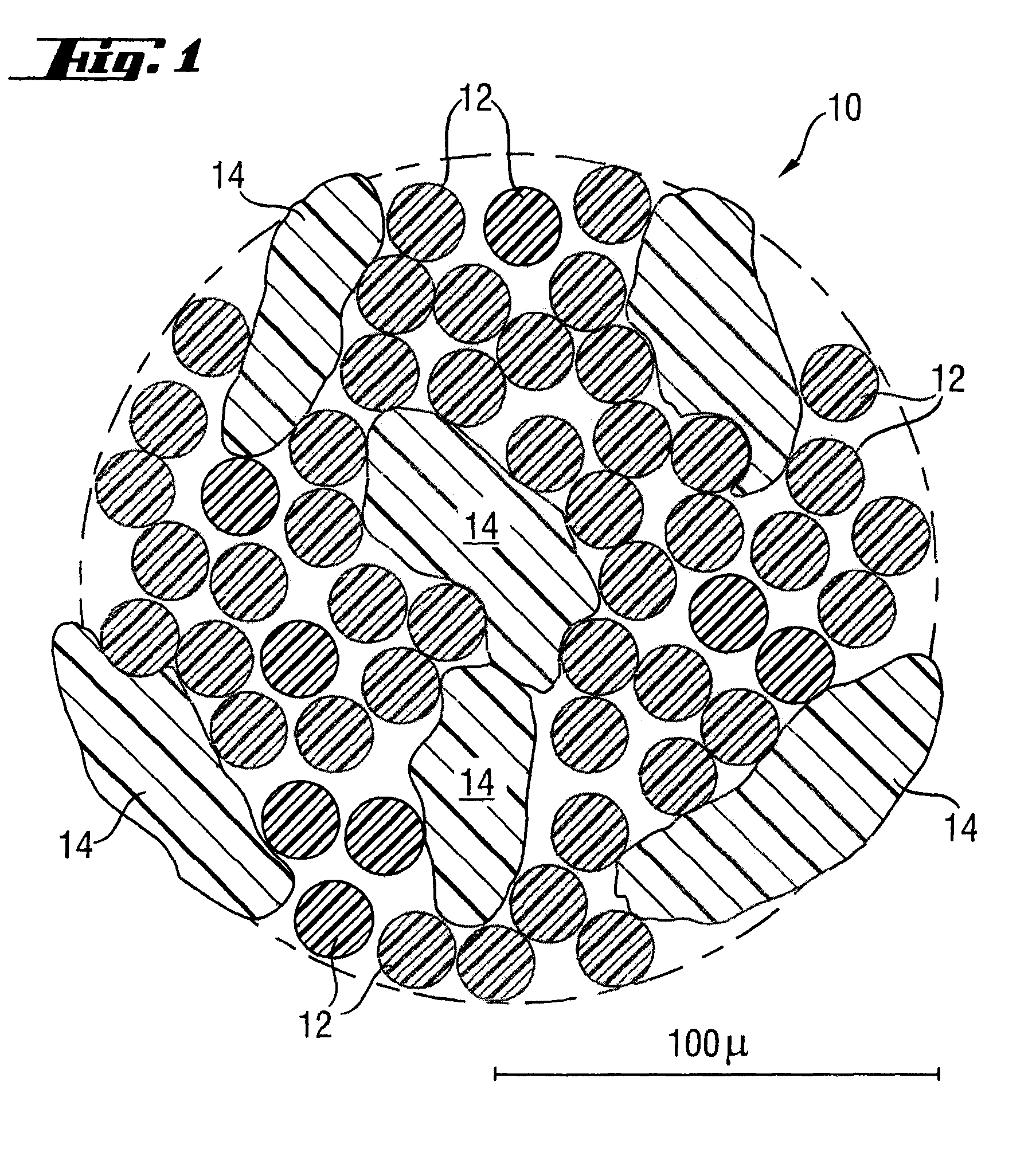
[0045]Plastic thread 10 used according to the invention for the sliding layer of the outer race as a reinforcing element is shown in FIG. 1 in an enlarged sectional representation. This consists of polyester filaments 12 orientated along the thread and contains as a second component PTFE particles 14 which are spun into polyester filaments 12 in a random arrangement. During the production process there are very many possibilities of modifying the properties of the thread. For example, the number of polyester filaments 12 per thread 10 can be varied according to the application, but here attention should be paid to ensuring an adequate positive engagement with the bound in PTFE particles 14.

[0046]The weight ratio of polyester filaments 12 to PTFE particles 14 may also be varied. However, it has proved particularly preferable, in terms of adhesion, friction and sliding characteristic, if the proportion of the PTFE particles 14 in the plastic thread is between 30 and 36% by weight and ...


PUM

PropertyMeasurementUnit
weight ratioaaaaaaaaaa
weightaaaaaaaaaa

Abstract

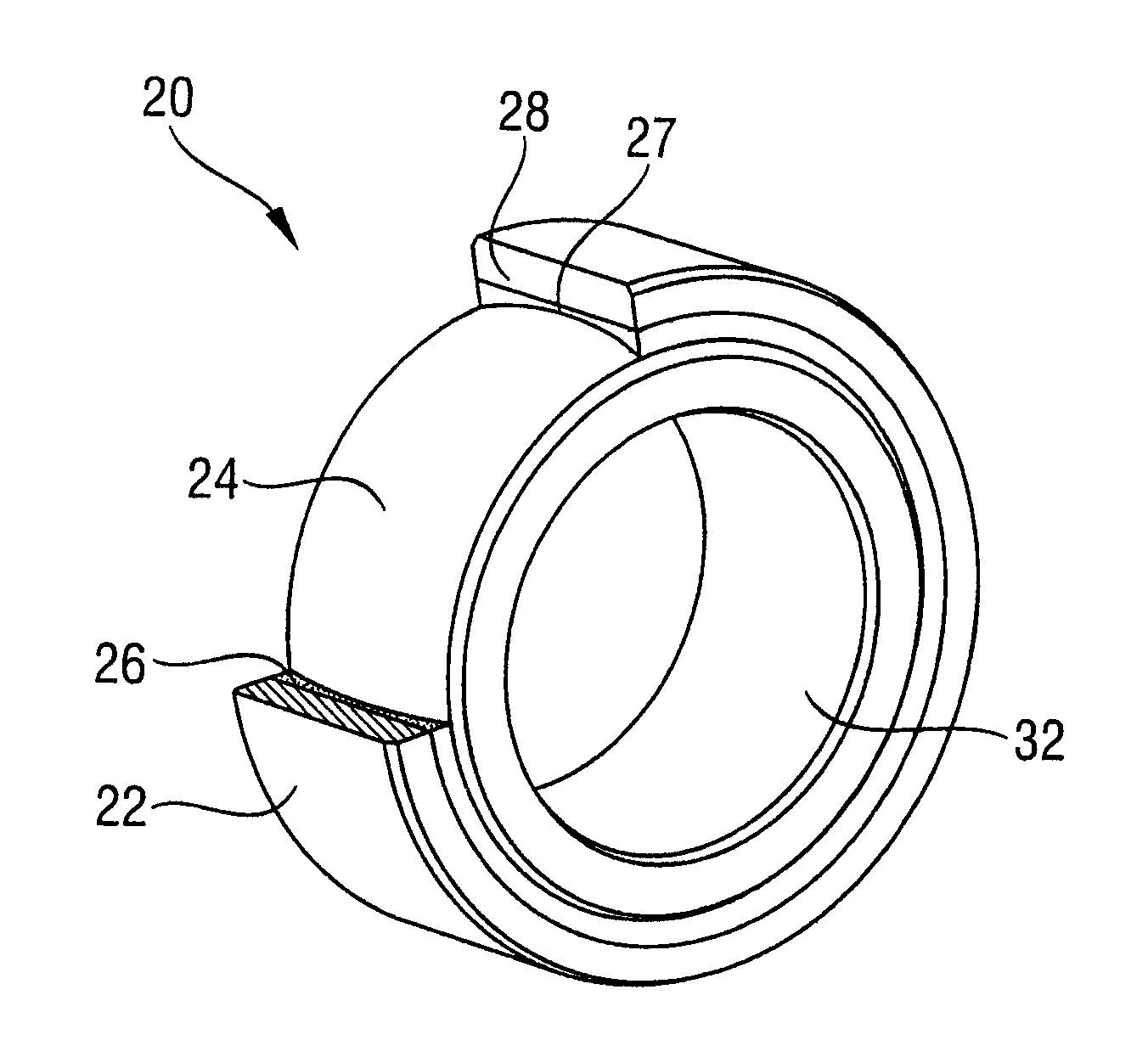
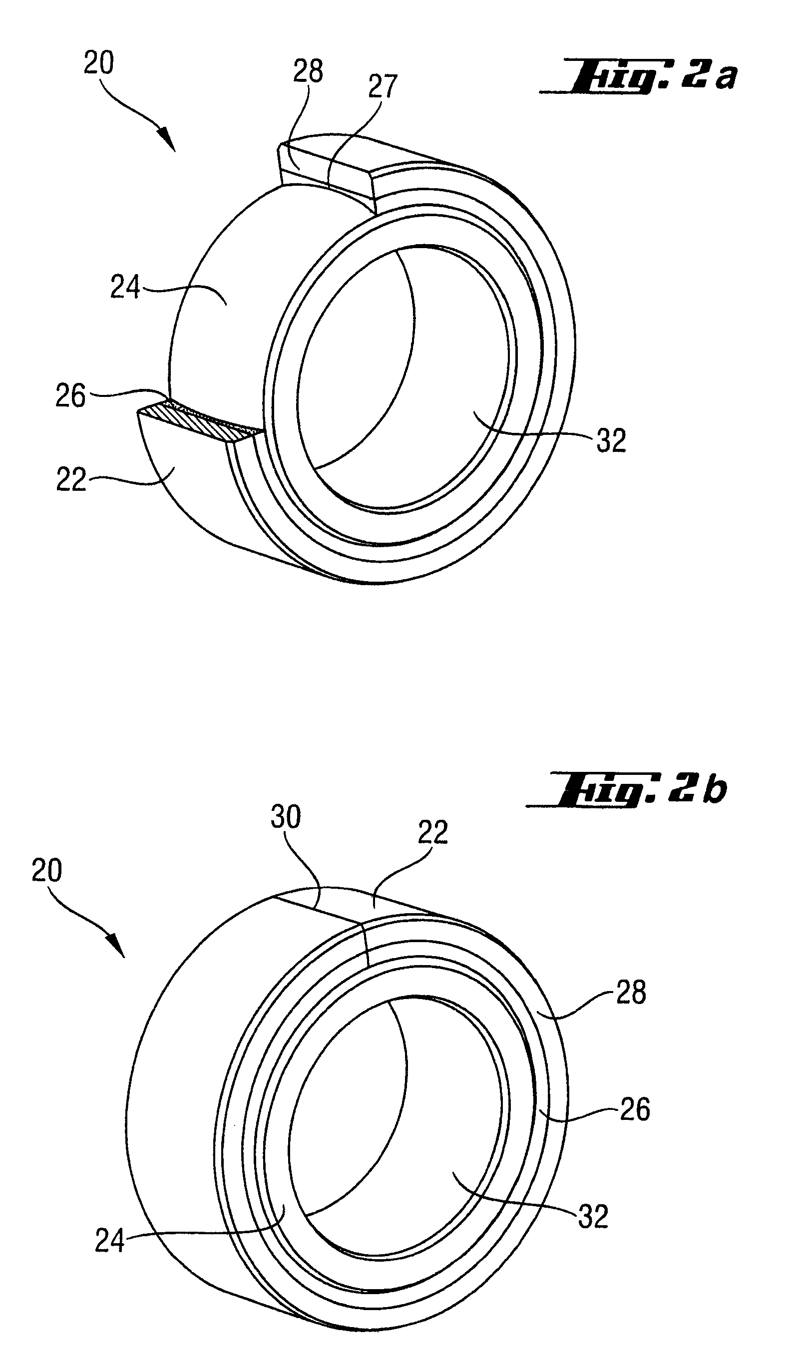
An outer race for a rocker bearing includes an internal sliding layer and an external support layer, wherein the sliding layer and the bearing layer are formed from a wound composite fiber material. The outer race is identified by exactly one parting line. A rocker bearing with such an outer race and a method for its production is also provided, in which a sliding layer and a support layer of synthetic resin impregnated fibers are wound in succession onto a winding mandrel, and outer races are formed after setting on the winding body thus produced. The sliding layer and the support layer are wound onto a cylindrical winding mandrel, and the outer race is provided with exactly one parting line opening it, and sliding layer material on its inside is removed to such an extent that a partially spherical contour is obtained for receiving a complementary inner race.

Description

RELATED APPLICATIONS[0001]This application claims priority to German Patent Application 10 2006 043 065.4-43, filed Sep. 14, 2006; German Patent Application 10 2006 042 999.0-43, filed Sep. 14, 2006 and German Patent Application 10 2007 008 584.4-12, filed Feb. 15, 2007.BACKGROUND OF THE INVENTION[0002]1. Technical Field[0003]The invention relates to an outer race for a rocker bearing or such a rocker bearing in which the outer race has an internal sliding layer and an external support layer, and in which the sliding layer and the support layer are formed from a wound compound fiber material. The invention also relates to a method for producing such an outer race, in which a sliding layer and a support layer of fibers impregnated in synthetic resin are wound on to a winding mandrel and outer races are formed from the winding body thus produced after hardening.[0004]2. Related Art[0005]Such a method is disclosed, for example, in DE 42 20 327. In the method disclosed there for produci...

Claims


Application Information

Patent Timeline
Patent Type & Authority Patents(United States)
IPC IPC(8): F16C33/20F16C23/02
CPCB29C69/003B29C70/32F16C23/04F16C33/201B29C53/58B29C70/08B29C2793/009B29K2033/00B29K2227/18B29K2427/18B29L2009/00B29L2031/04B29L2031/7096F16C23/046F16C33/046Y10S384/908F16C2208/86
Inventor LAAL RIAHI, KAMRANSTADLMAYR, AUGUST
Owner FEDERAL MOGUL DEVA
Learn More