Flat type vibration motor

a vibration motor and flat-type technology, applied in the direction of electrical equipment, dynamo-electric machines, supports/enclosements/casings, etc., can solve the problems that the vibration force generated by the rotor b>16/b> cannot be securely transmitted to the cellular phone set, and the manual work of the vibration motor, etc., to achieve the effect of improving the connection force and reducing electromagnetic wave nois

Inactive Publication Date: 2012-07-24
MPLUS
View PDF5 Cites 1120 Cited by
  • Summary
  • Abstract
  • Description
  • Claims
  • Application Information

AI Technical Summary

Benefits of technology

[0016]The present invention has been made in an effort to provide a flat type vibration motor capable of improving the connection force between a bracket and a printed circuit board by adopting a contact portion connected with a terminal portion and reducing electromagnetic wave noise.

Problems solved by technology

However, the vibration motor needs a manual work in a process of fixing the vibration motor to the cellular phone set and a process of soldering the lead wire.
Moreover, since the motor is fixed to the PCB of the cellular phone set by soldering only an external power connection terminal of the printed circuit board 11, fixation force is weak and as a result, when vibration is generated or an impact is received, the motor may be separated from the PCB and the vibration force generated from the rotor 16 cannot be securely transmitted to the cellular phone set.

Method used


Image

  • Flat type vibration motor
  • Flat type vibration motor
  • Flat type vibration motor

Examples


first embodiment

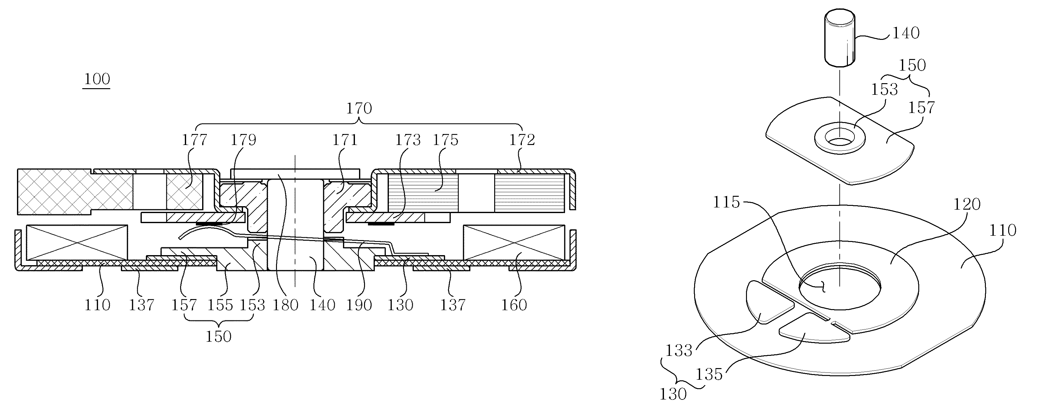
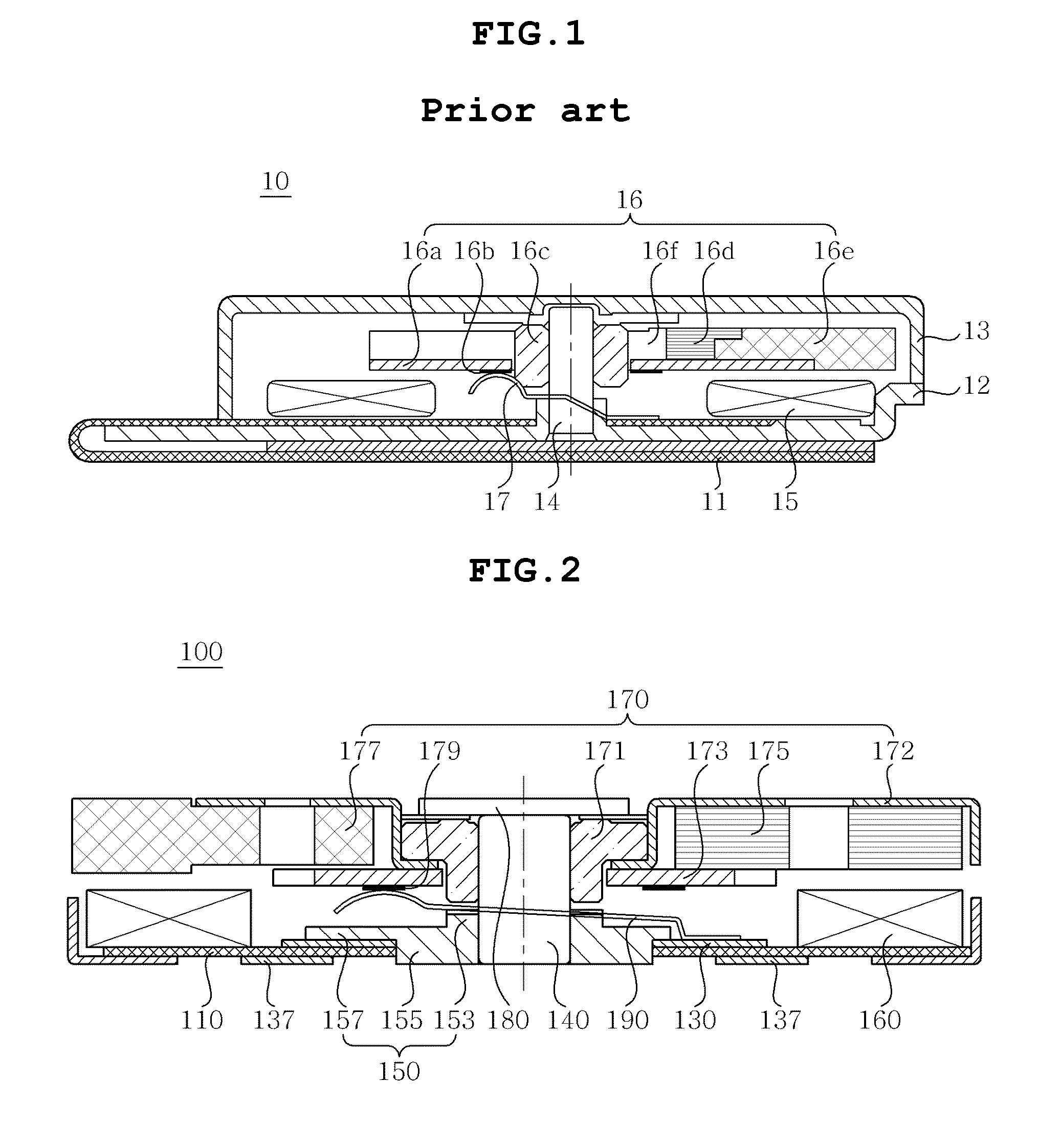
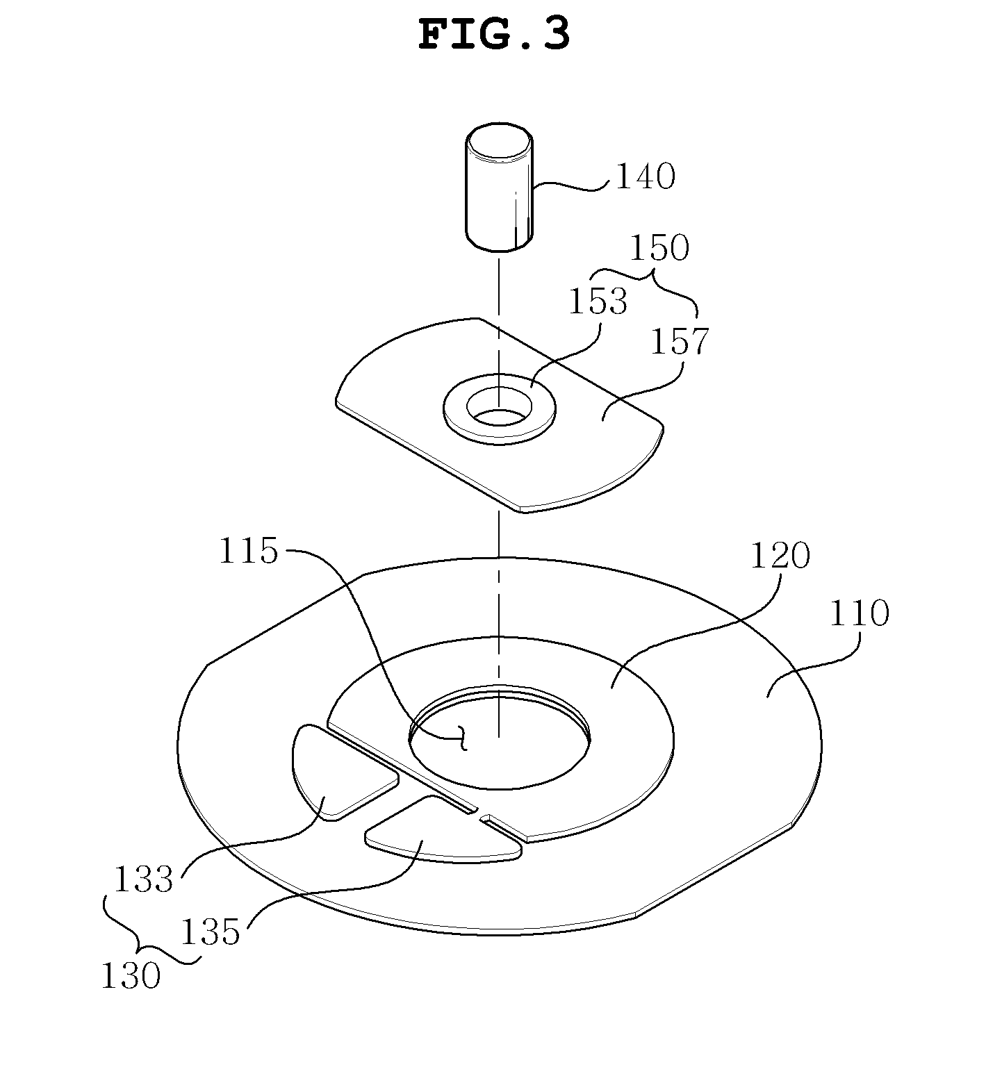
[0039]FIG. 2 is a cross-sectional view of a flat type vibration motor according to the present invention, FIG. 3 is an exploded perspective view illustrating the connection relationship among a printed circuit board, a bracket, and a shaft shown in FIG. 2, FIG. 4 is an exploded bottom perspective view illustrating the connection relationship among a printed circuit board, a bracket, and a shaft shown in FIG. 2, and FIG. 5 is a connection perspective view illustrating the connection relationship among a printed circuit board, a bracket, and a shaft shown in FIG. 2.

[0040]As shown in FIGS. 2 to 5, the flat type vibration motor 100 according to the embodiment of the present invention includes a bracket 150 a shaft 140 of which one end is inserted into and fixed to the center thereof, a printed circuit board 110 having a terminal portion 130 receiving external electricity and disposed on the side of the bracket 150, a stator disposed on the top of the printed circuit board 110, a rotor 1...

second embodiment

[0054]FIG. 6 is a cross-sectional view of a flat type vibration motor according to the present invention.

[0055]As shown in FIG. 6, the largest difference between the flat type vibration motor 100 according to the first embodiment and the flat type vibration motor 200 according to the embodiment is whether or not the case 185 is provided. That is, the flat type vibration motor 100 according to the first embodiment does not have the case 185, while the flat type vibration motor 200 according to the embodiment has the case 185. Since other components except whether or not the case 185 is provided are similar to those of the first embodiment, duplicate description will be omitted and a difference will principally be described.

[0056]The case 185 is a receiving member providing a rotation space of the rotor 170 by covering the rotor 170 so as to protect the rotor 170, the shaft 140, and the like from the outside. Herein, the case 185 has large permeability so as to form a magnetic path of...


PUM


Abstract

There is provided a flat type vibration motor 100 that includes a bracket 150 with a shaft 140 of which one end is inserted into and fixed to the center thereof, a printed circuit board 110 having a terminal portion 130 receiving external electricity and disposed on the side of the bracket 150, a stator disposed on the top of the printed circuit board 110, a rotor 170 rotatably installed in the shaft 140 and generating vibration while rotating by interaction with the stator 160, and a stopper 180 installed at the other end of the shaft 140. The bracket 150 and the shaft 140 are electrically connected with the terminal portion 130. Further, it is possible to use the bracket or a shaft as an external power connection terminal by electrically connecting a negative terminal to the bracket and the shaft through the contact portion.

Description

CROSS REFERENCE TO RELATED APPLICATION[0001]This application claims the benefit of Korean Patent Application No. 10-2010-0053457, filed on Jun. 7, 2010, entitled “Flat Type Vibration Motor”, which is hereby incorporated by reference in its entirety into this application.BACKGROUND OF THE INVENTION[0002]1. Technical Field[0003]The present invention relates to a flat type vibration motor.[0004]2. Description of the Related Art[0005]In portable electronic apparatuses such as a cellular phone, a game machine, a portable information terminal, etc., various types of vibration generation devices are mounted on the portable electronic apparatuses in order to prevent disturbing other people due to sound. In particular, the vibration generation device is mounted in the cellular phone sp as to be used as a silent receiving signal generating device and with miniaturization and slimming tendencies of the cellular phones, vibration generating devices mounted therein also require miniaturization a...

Claims


Application Information

Patent Timeline
Patent Type & Authority Patents(United States)
IPC IPC(8): H02K7/06
CPCH02K5/1677H02K5/225H02K7/086H02K7/063H02K2211/03
Inventor KIM, YONG TAE
Owner MPLUS
Why Eureka
Try Eureka