Split type bearing cage connection scheme

A technology of bearing frames and rolling bearings, applied in the direction of bearings, bearing assembly, shafts and bearings

Inactive Publication Date: 2013-04-10
AB SKF
View PDF5 Cites 8 Cited by
  • Summary
  • Abstract
  • Description
  • Claims
  • Application Information

AI Technical Summary

Problems solved by technology

However, since the crankshaft is basically designed to be cur

Method used


Image

  • Split type bearing cage connection scheme
  • Split type bearing cage connection scheme
  • Split type bearing cage connection scheme

Examples


Embodiment Construction

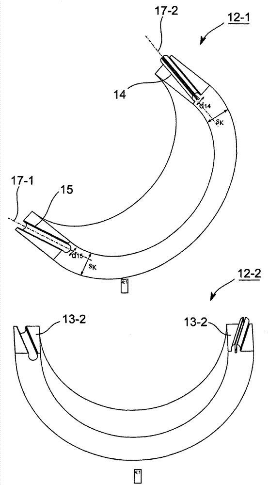
[0037] figure 1 A three-dimensional schematic diagram showing an embodiment of a split bearing frame 10 for guiding the rolling bodies of a rolling bearing.

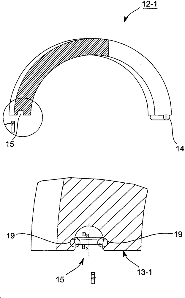
[0038] The bearing frame 10 is slit in the circumferential or tangential direction, for example at two separation locations 11-1, 11-2 between the first bearing frame section 12-1 and the second bearing frame section 12-2 or constructed separately. Formed respectively on the mutually (circumferentially) facing interface surfaces 13-1, 13-2 of the separation locations 11-1, 11-2 between the first and second bearing frame sections 12-1, 12-2 There is a pair consisting of a protrusion 14 and a corresponding and (circumferentially) opposite recess 15 for forming a contact in three directions (axial, radial and tangential) when the protrusion 14 and the corresponding recess 15 are engaged with each other. Fix or arrange the interface surfaces 13-1, 13-2 upward to each other. The protrusion 14 and its corresponding recess 1...


PUM


Abstract

The present invention relates to a bearing cage used for a rolling bearing. The bearing cage (10) has at least one interface (11-1, 11-2) slotted between two bearing cage portions (12-1, 12-2) in a circumferential direction. A projection (14) and a corresponding recess (15) are respectively formed on boundary surfaces (13-1, 13-2) of each interface, where the boundary surfaces face each other. The projection and the recess are fixable with each other in three directions. Major axes (17-1, 17-2) of the projection and the recess are diagonally extended at an angle (alpha) with respect to a rotational axis (16) of the cage.

Description

technical field [0001] The invention relates to a slotted bearing frame, in particular for rolling bearings, and to the manufacture of such a bearing frame. Background technique [0002] A bearing frame for a rolling bearing generally consists of two side rings spaced apart in the axial direction and a plurality of bridging pieces connected to the side rings and arranged sequentially in the circumferential direction of the bearing frame. These bridging pieces are formed in pairs. In the recess that accommodates the rolling elements. The bearing carrier keeps the rolling elements at a distance from each other and prevents adjacent rolling elements from coming into direct contact with each other by means of the recesses provided for this purpose, so that friction and the resulting heat in the bearing can generally be reduced. In addition, it distributes the rolling elements evenly over the entire circumference of the bearing frame or rolling bearing and enables uniform load d...

Claims


Application Information

Patent Timeline
IPC IPC(8): F16C33/50F16C33/46B25B7/00B25B7/02
CPCB25B7/00F16C2226/76F16C2226/74F16C33/504F16C2240/30F16C33/4623B25B27/0035F16C2360/22F16C2240/42F16C43/04Y10T29/53104F16C33/30
Inventor J·斯托克B·埃克
Owner AB SKF
Why Eureka
Try Eureka