Eddy current flaw detection probe

a flaw detection and eddy current technology, applied in the direction of mechanical measuring arrangements, mechanical roughness/irregularity measurements, instruments, etc., can solve the problems of increasing the inspection time, affecting the inspection accuracy, and causing the difference between the inner pressure of the sac-like object and the water pressur

Active Publication Date: 2012-07-24
HITACHI-GE NUCLEAR ENERGY LTD
View PDF10 Cites 3 Cited by
  • Summary
  • Abstract
  • Description
  • Claims
  • Application Information

AI Technical Summary

Benefits of technology

[0005]For eddy current flaw detection based on the use of a multiple coil, it is important that a constant distance (lift-off) be maintained between the coil and the inspection target. To achieve such a purpose, the eddy current flaw detection probe disclosed in JP-A-2006-194661 uses a Bakelite or other similar rigid body prepared to fit the curvature of an inspection section as an elastic body positioned opposite an inspection target for the probe. Therefore, curvature changes can be handled as far as they can be absorbed by the elastic body. However, when a significant curvature change is encountered, it is necessary to change the Bakelite or other similar rigid body. This causes the inspection time to increase.
[0009]The use of the above configuration makes it possible to press the probe against an inspection target whose curvature varies.
[0015]The present invention makes it possible to press the probe against an inspection target whose curvature varies.

Problems solved by technology

However, when a significant curvature change is encountered, it is necessary to change the Bakelite or other similar rigid body.
This causes the inspection time to increase.
However, if, for instance, the probe is used at a water depth of up to approximately 30 m for nuclear plant reactor inspection purposes, a great difference arises between the inner pressure of the sac-like object and the water pressure.
This increases the inspection time.
Further, if a leaf spring is used, the pressing force applied to an inspection target whose curvature varies becomes significantly uneven.
This makes it difficult to maintain a constant lift-off.
Consequently, inaccurate inspection results may be obtained.

Method used


Image

  • Eddy current flaw detection probe
  • Eddy current flaw detection probe
  • Eddy current flaw detection probe

Examples


first embodiment

[0037]The configuration of an eddy current flaw detection probe according to the present invention will now be described with reference to FIGS. 1 to 7.

[0038]First of all, the overall configuration of the eddy current flaw detection probe according to the first embodiment will be described with reference to FIG. 1.

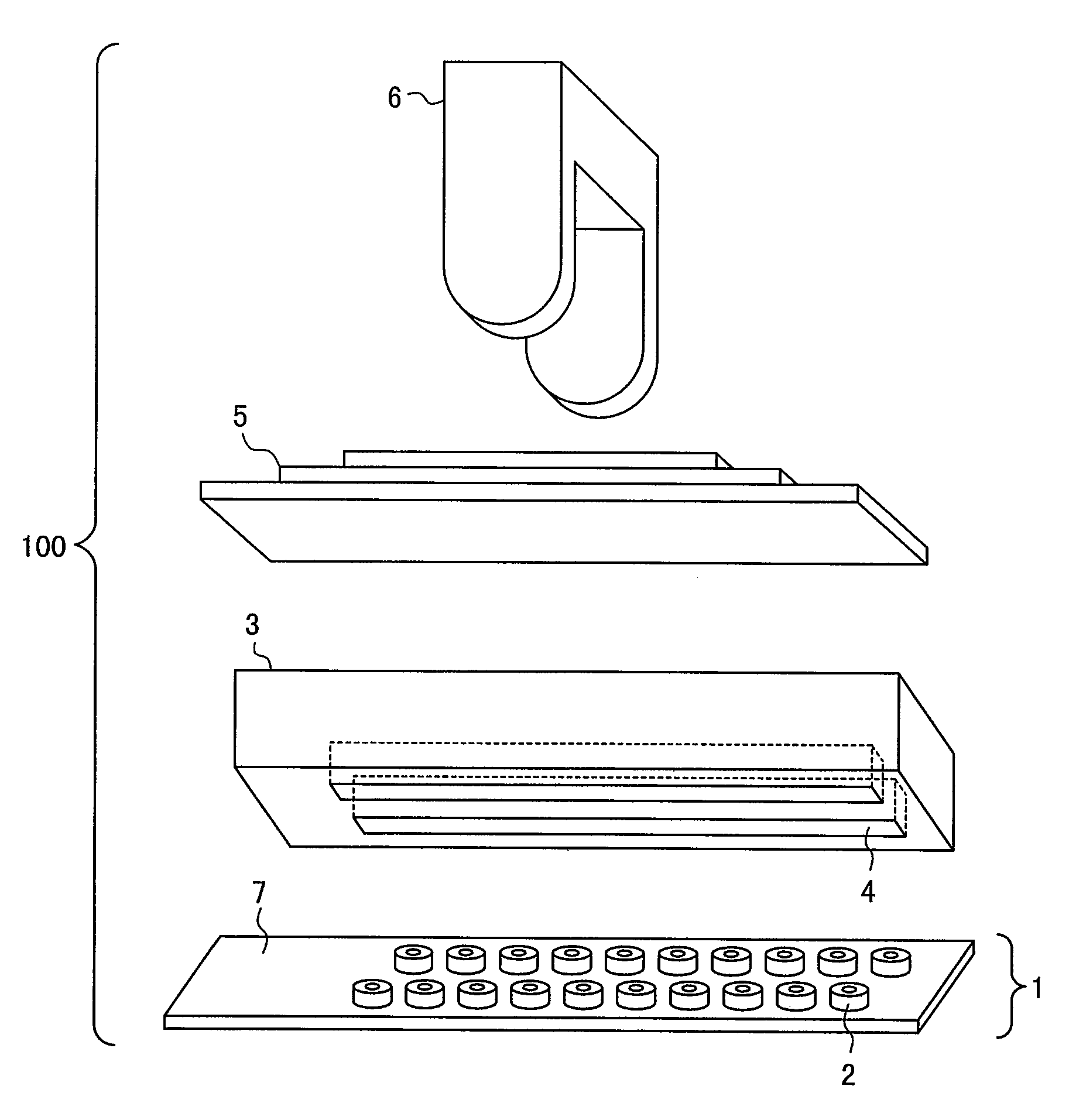
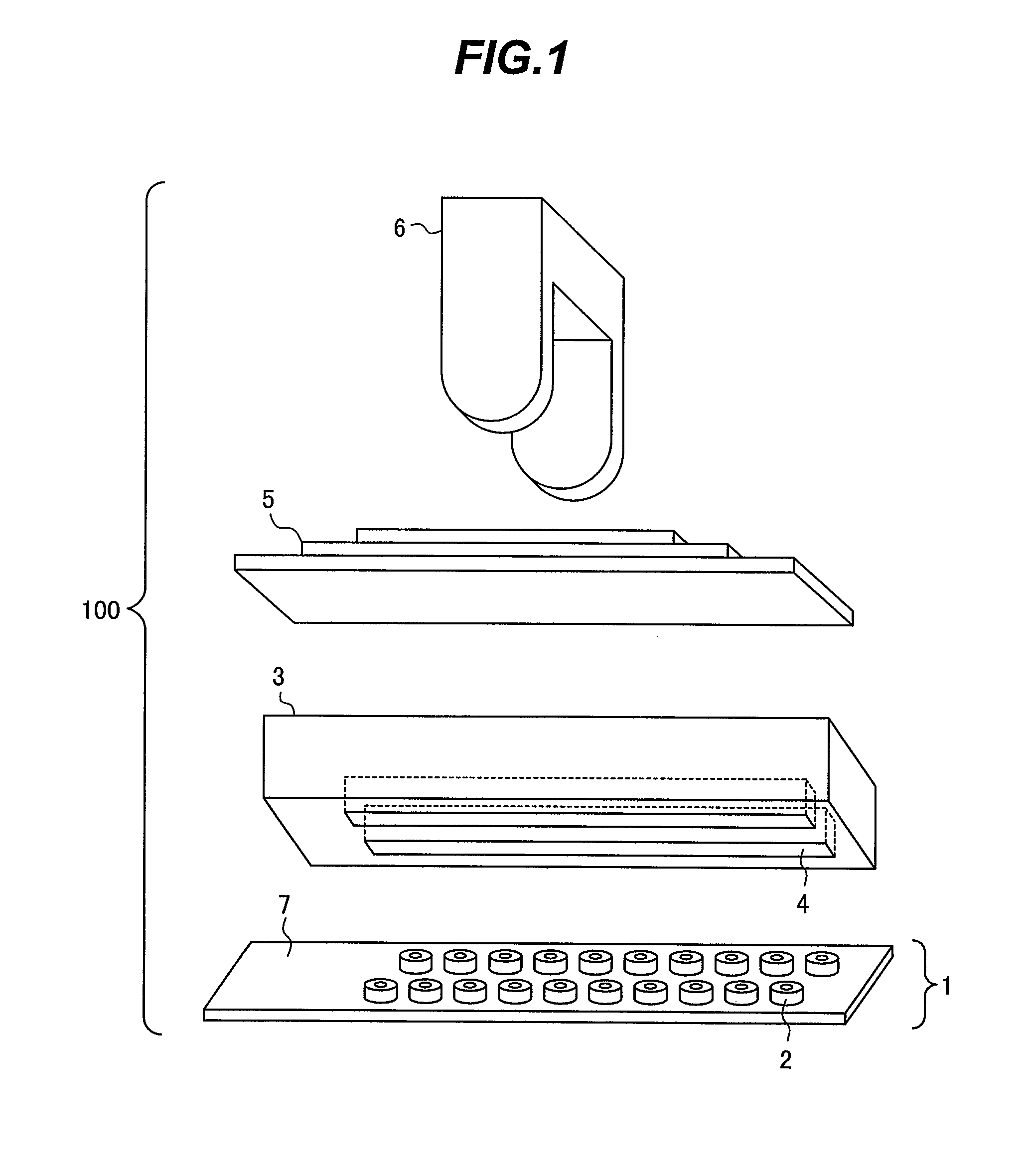
[0039]FIG. 1 is an exploded perspective view showing the overall configuration of the eddy current flaw detection probe according to the first embodiment of the present invention.

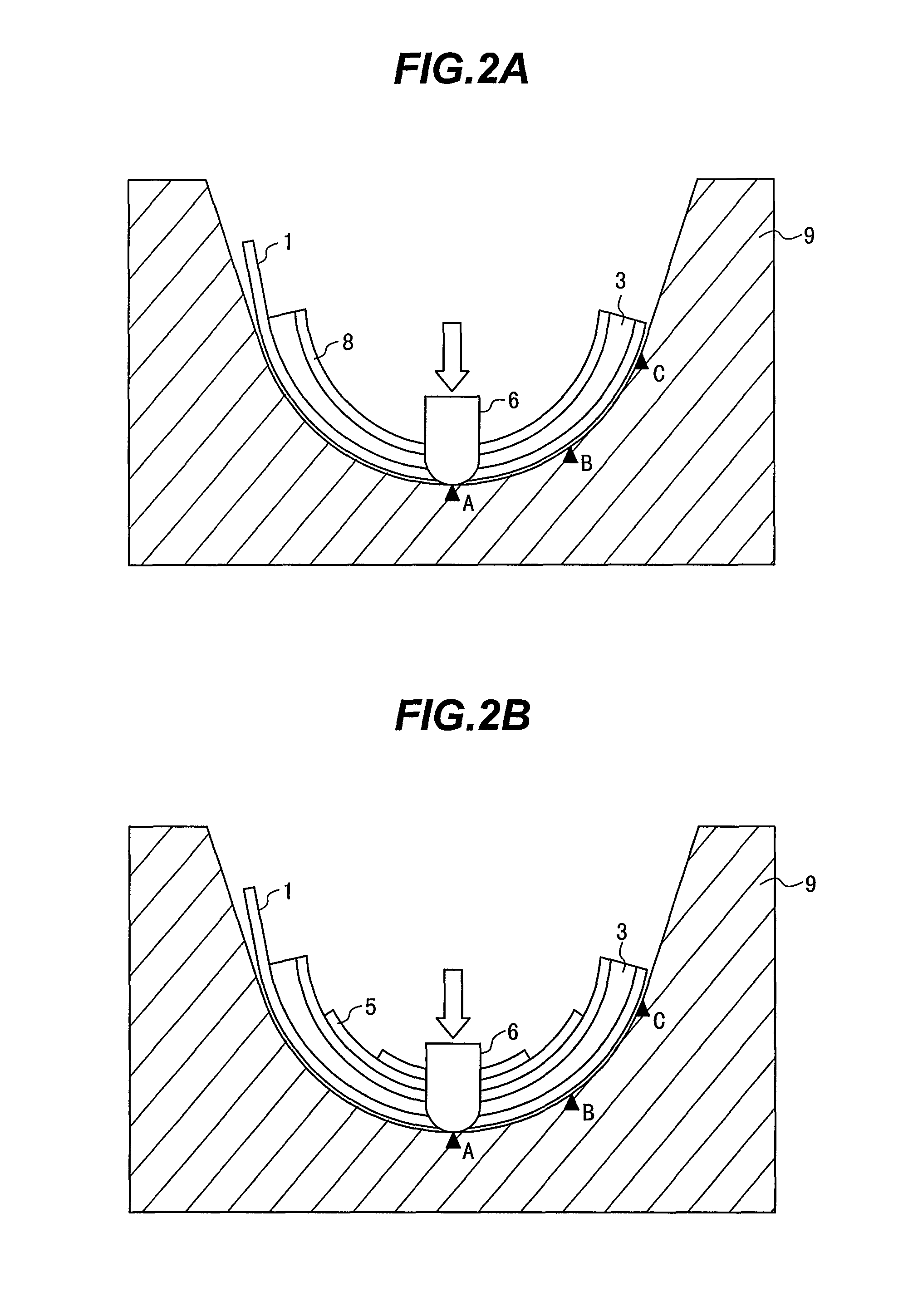
[0040]The eddy current flaw detection probe 100 includes a flaw sensor 1, which faces the surface of an inspection target; elastic bodies 3, 5, which bring the flaw sensor 1 into contact with the inspection target; and a pressure section 6, which presses the flaw sensor 1 against the inspection target via the elastic bodies 3, 5.

[0041]The flaw sensor 1 includes a flexible substrate 7, which is formed by stacking multiple layers of polyimide film or the like; and a plurality of coils 2, which are f...

second embodiment

[0064]The configuration of an eddy current flaw detection probe according to the present invention will now be described with reference to FIGS. 8 to 10.

[0065]FIG. 8 is an exploded perspective view showing the overall configuration of the eddy current flaw detection probe according to the second embodiment of the present invention. FIG. 9 is a side view showing the eddy current flaw detection probe according to the second embodiment of the present invention. FIG. 10 is a side view showing how the eddy current flaw detection probe according to the second embodiment of the present invention is pressed against an inspection target. Like elements in FIGS. 1, 8, 9, and 10 are identified by the same reference numerals.

[0066]As shown in FIG. 8, the eddy current flaw detection probe 100A according to the present embodiment is effective in a situation where an inspection target having a curved surface in the longitudinal direction of the probe cannot be vertically pressed. This eddy current ...

third embodiment

[0072]The configuration of an eddy current flaw detection probe according to the present invention will now be described with reference to FIGS. 11 to 13.

[0073]FIG. 11 is an exploded perspective view showing the overall configuration of the eddy current flaw detection probe according to the third embodiment of the present invention. FIG. 12 is a side view showing the eddy current flaw detection probe according to the third embodiment of the present invention. FIG. 13 is a side view showing how the eddy current flaw detection probe according to the third embodiment of the present invention is pressed against an inspection target. Like elements in FIGS. 1, 8, 11, 12, and 13 are identified by the same reference numerals.

[0074]As shown in FIG. 11, the eddy current flaw detection probe 100B according to the present embodiment is effective in a situation where an inspection target having a curved surface in the longitudinal and transverse directions of the probe cannot be vertically press...


PUM

PropertyMeasurementUnit
thicknessaaaaaaaaaa
thicknessaaaaaaaaaa
thicknessaaaaaaaaaa

Abstract

Disclosed is an eddy current flaw detection probe that is capable of pressing itself against an inspection target whose curvature varies. A flaw sensor is configured by fastening a plurality of coils to a flexible substrate that faces the surface of the inspection target. A first elastic body is positioned opposite the inspection target for the flaw sensor, is obtained by stacking two or more elastic plates, and has an elastic coefficient that varies in a longitudinal direction. A second elastic body is a porous body positioned between the flexible substrate and the first elastic body. A pressure section is employed to press the first elastic body toward the inspection target.

Description

BACKGROUND OF THE INVENTION[0001]1. Field of the Invention[0002]The present invention relates to an eddy current flaw detection probe, and more particularly to an eddy current flaw detection probe that detects a flaw in an inspection target by sequentially selecting one of a plurality of coils and detecting a flaw detection signal from a detection coil.[0003]2. Description of the Related Art[0004]Some known eddy current flaw detection probes for detecting a flaw in an inspection target by sequentially selecting one of a plurality of coils (included in a multiple coil) and detecting a flaw detection signal from a detection coil employ a plurality of coils arranged on a flexible substrate, press the coils against the surface of an inspection target by using the elasticity, for instance, of a leaf spring, sequentially select one of the plurality of coils, and achieve flaw detection by detecting a flaw detection signal from a detection coil (refer, for instance, to JP-A-2006-194661 and ...

Claims


Application Information

Patent Timeline
Patent Type & Authority Patents(United States)
IPC IPC(8): G01R33/02G01N27/82
CPCG01N27/9033G01N27/9006
Inventor NISHIMIZU, AKIRAOUCHI, HIROFUMINONAKA, YOSHIOTAKATORI, YOSUKETAKI, AKIHIROSENOO, MAKOTO
Owner HITACHI-GE NUCLEAR ENERGY LTD
Why Eureka
Try Eureka