Image inspecting apparatus, image inspecting method and image inspecting program

a technology of image inspection and inspection apparatus, applied in the direction of image enhancement, instruments, image data processing, etc., can solve the problems of reducing defect detection accuracy, requiring a great deal of time for image capture, and complicated process

Active Publication Date: 2019-09-12
ORMON CORP
View PDF5 Cites 2 Cited by
  • Summary
  • Abstract
  • Description
  • Claims
  • Application Information

AI Technical Summary

Benefits of technology

[0031]In the image inspecting apparatus, the image inspecting method and the image inspecting program, the increase in inspection time and the decrease in detection accuracy can be suppressed as much as possible in the case where the irradiated place at which to the object under inspection is irradiated with the pattern light is a curved surface.

Problems solved by technology

Therefore, to detect a defect, a complicated process, such as a filtering process for removing the influence due to pattern distortion, is required.
However, in the case in which the place at which the pattern light is irradiated is a curved surface, since the width of the stripe may increase and decrease in the image in which the irradiated place is photographed, the defect detection accuracy decreases due to the width variation of the stripe.
Therefore, in the case in which the place irradiated with the pattern light is a curved surface, while it may be considered to irradiate the object under inspection with pattern light in strips of various widths, tremendous time is required for image capturing because of the increase in the types of pattern light irradiated to the object under inspection.

Method used


Image

  • Image inspecting apparatus, image inspecting method and image inspecting program
  • Image inspecting apparatus, image inspecting method and image inspecting program
  • Image inspecting apparatus, image inspecting method and image inspecting program

Examples


application example

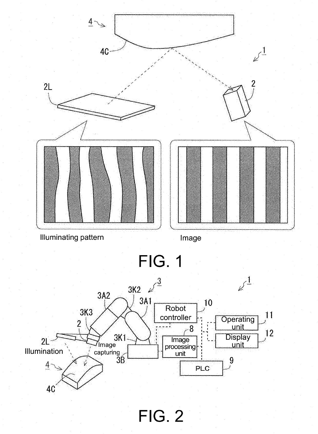
[0032]FIG. 1 is a Schematic View Showing an Example of a Process realized by an image inspecting apparatus 1 according to the embodiment. As shown in FIG. 1, the image inspecting apparatus 1 includes a camera 2 (an example of the “image capturing part” in the disclosure) and a lighting 2L (an example of the “lighting part” of the disclosure), for example, as the main configuration. The camera 2 obtains an image used for inspecting an object 4 under inspection. The lighting 2L irradiates the object 4 under inspection with light in a predetermined illuminating pattern.

[0033]The image data obtained by capturing the image of the object 4 under inspection illuminated by the lighting 2L by using the camera 2 is sent to an image processing unit (not shown) provided in the image inspecting apparatus 1. In the image processing unit, the appearance of the object 4 under inspection is inspected by using the image data sent from the camera 2. The object 4 under inspection for which whether a de...

embodiment

[0039]The image inspecting apparatus 1 will be described in detail below. FIG. 2 is a view showing an example of the overall configuration of the image inspecting apparatus 1. The image inspecting apparatus 1 includes, in addition to the camera 2 and the lighting 2L described above, a robot arm 3 in which the camera 2 and the lighting 2L are provided at a tip, an image processing unit 8 (an example of the “determining part” of the disclosure) in charge of processing of the image data sent from the camera 2, a robot controller 10 controlling the robot arm 3, and a programmable logic controller (PLC) 9 (an example of the “control part” in the disclosure) in charge of control of the camera 2, the lighting 2L, and the robot controller 10. The image processing unit 8 may be, for example, a general-purpose computer having a central processing unit (CPU), a memory, an auxiliary storage apparatus (e.g., a hard disk drive, a solid state drive, etc.), and an input apparatus (a keyboard, a mou...


PUM


Abstract

An image inspecting apparatus for inspecting an object under inspection by using an image, including: a lighting part which irradiates the object under inspection with light; an image capturing part which captures an image of the object under inspection; and a control part which causes the lighting part to irradiate pattern light in a shape that is created based on a positional relationship between the lighting part and the image capturing part and shape data of the object under inspection and that in a case where the lighting part irradiates light, a shape of the light of the lighting part photographed in the image captured by the image capturing part matches a predetermined pattern, is provided.

Description

CROSS-REFERENCE TO RELATED APPLICATION[0001]This application claims the priority benefit of Japanese Patent Application serial no. 2018-039347, filed on Mar. 6, 2018. The entirety of the above-mentioned patent application is hereby incorporated by reference herein and made a part of this specification.BACKGROUNDTechnical Field[0002]The disclosure relates to an image inspecting apparatus, an image inspecting method, and an image inspecting program.Description of Related Art[0003]In recent years, an image inspecting apparatus which inspects the appearance of a product by using an image has been widely used in order to automatize the inspection and save the labor in the production line (see, for example, Patent Document 1: Japanese Laid-Open No. 2013-191064). While there are various types and methods of appearance inspection, the basic configuration is as follows. The image of an object under inspection is captured by an image capturing apparatus with a built-in image sensor, a portion...

Claims


Application Information

Patent Timeline
Patent Type & Authority Applications(United States)
IPC IPC(8): G06T7/60G06T7/70
CPCG06T2207/30204G06T7/60G06T7/70G01N21/956G01B11/2513G01N21/8806G01N2021/8829G01N2021/9518G01N21/9515
Inventor KATO, YUTAKA
Owner ORMON CORP
Why Eureka
Try Eureka