
Semi-actuated transfemoral prosthetic knee

a prosthetic knee and transfemoral technology, applied in the field of prosthetics, can solve the problems of fluid system control, and achieve the effect of reducing the necessary hip torque and power, less electric power, and efficient creation

Active Publication Date: 2012-07-31
EKSO BIONICS +1
View PDF33 Cites 39 Cited by
  • Summary
  • Abstract
  • Description
  • Claims
  • Application Information

AI Technical Summary

Benefits of technology

The present invention is about a prosthetic system that is mostly passive in nature, meaning it only requires power for locomotion during a portion of a walking cycle. The prosthetic includes a shank link, a knee mechanism, and a thigh link. The knee mechanism is designed to provide flexion and extension movements of the thigh and shank links relative to each other. The prosthetic can operate in either an actuated mode or an un-actuated mode. In the actuated mode, power is delivered to a torque generator connected to the knee mechanism to cause a forced movement between the thigh and shank links. In the un-actuated mode, a control circuit operates in a non-powered manner to allow operation of the knee mechanism with modulated resistance. The prosthetic system is operable in either an actuated mode or an un-actuated mode based on signals received from sensors provided on the prosthetic. The system employs less electric power than fully powered knees and is smaller in size. It also reduces necessary hip torque and power that the amputee must physically exert by efficiently creating synchronized torque and power during an effective portion of a walking cycle. The various sensors provide inputs to the signal processor that maximize the range and type of motions generated for the amputee.

Problems solved by technology

However, fluctuations in the speed of movement may be needed as well such that proper control of the fluid system is also needed.

Method used


Image

  • Semi-actuated transfemoral prosthetic knee
  • Semi-actuated transfemoral prosthetic knee
  • Semi-actuated transfemoral prosthetic knee

Examples


Embodiment Construction

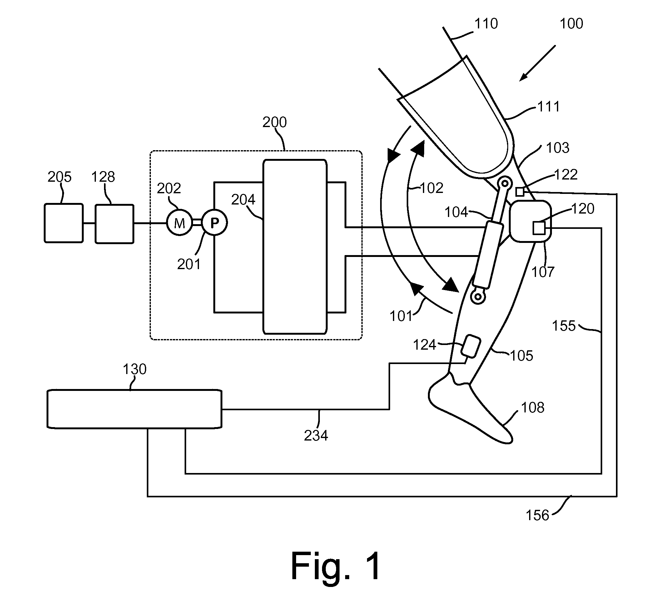
[0051]With initial reference to FIG. 1, a semi-actuated prosthetic knee 100 constructed in accordance with a first embodiment of the invention is configurable to be coupled to an above-knee amputee's remaining lower limb 110 through a socket 111. Semi-actuated prosthetic knee 100, among other components, comprises a thigh link 103 coupled to a knee mechanism 107 and a shank link 105 coupled to an artificial foot 108. Knee mechanism 107 is configured to allow flexion and extension movements of thigh link 103 and a shank link 105 relative to each other along flexion direction 101 and extension direction 102. A hydraulic torque generator 104 is configured to generate torque between thigh link 103 and shank link 105.

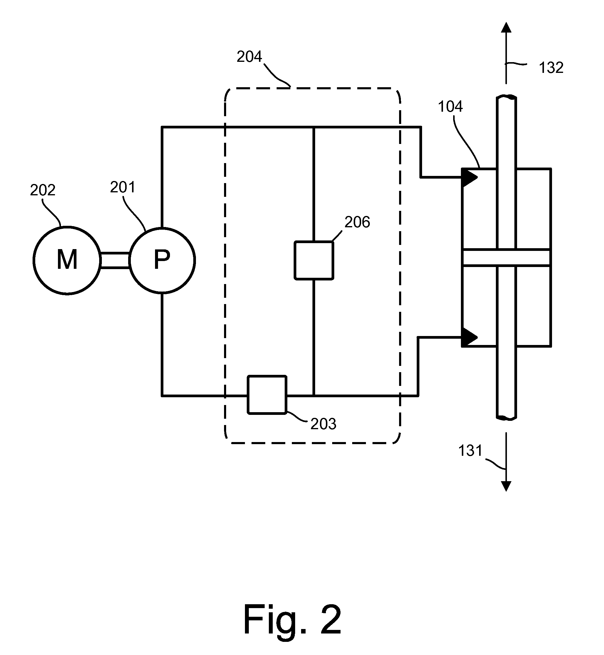
[0052]Semi-actuated prosthetic knee 100 further includes a hydraulic power unit indicated at 200 coupled to hydraulic torque generator 104. Hydraulic power unit 200, among other components, includes a hydraulic valve circuit 204, which is hydraulically coupled to torque gene...


PUM


Abstract

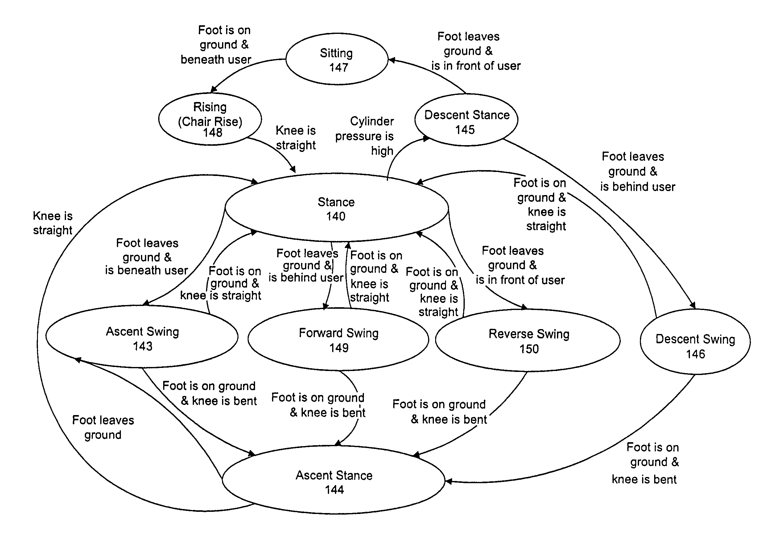
A semi-actuated above knee prosthetic system, which is mostly passive in nature and includes a shank link coupled to an artificial foot, a knee mechanism connected to the shank link and a thigh link attached to an above-knee remaining lower limb of an amputee, is operable in either an actuated mode or an un-actuated mode controlled by a signal processor linked to various prosthetic mounted sensors which may include combinations of knee angle, stance, thigh angle and shank angle sensors. Power is delivered through an electric motor connected to a battery source and employed to drive a hydraulic pump which is part of an overall hydraulic power unit including the torque generator. A signal processor selects a swing state from at least forward, combination forward and descent, combination forward and ascent, reverse, combination reverse and descent, and combination reverse and ascent swing states.

Description

CROSS-REFERENCE TO RELATED APPLICATIONS[0001]This application claims the benefit of U.S. Provisional Application No. 61 / 132,217 entitled SEMI-ACTUATED TRANSFEMORAL PROSTHETIC KNEE, filed on filed Jun. 16, 2008, and U.S. Provisional Application 61 / 136,535 entitled SEMI-ACTUATED TRANSFEMORAL PROSTHETIC KNEE, filed Sep. 12, 2008.STATEMENT REGARDING FEDERALLY SPONSORED RESEARCH OR DEVELOPMENT[0002]This invention was made with government support under Award No. W81XWH-05-C-0147 awarded by Telemedicine & Advanced Technology Research Center, Department of the Army and under Award No. CMS-0510848 awarded by the National Science Foundation. The government has certain rights in the invention.BACKGROUND OF THE INVENTION[0003]The present invention relates generally to the field of prosthetics and, more specifically, to controlling powered and non-powered operations of a prosthetic attached to an above-knee remaining lower limb of an amputee.[0004]In recent years, major advancements have been ma...

Claims


Application Information

Patent Timeline
Patent Type & Authority Patents(United States)
IPC IPC(8): A61F2/48A61F2/60A61F2/68
CPCA61F2/64A61F2/68A61F2/80A61F2002/30359A61F2002/701A61F2002/704A61F2220/0033A61F2002/744A61F2002/745A61F2002/748A61F2002/7625A61F2002/7635A61F2002/7645A61F2002/741A61F2/70A61F2/744A61F2/741A61F2/748A61F2/74
Inventor FAIRBANKS, DYLAN MILLERZOSS, ADAM BRIANPILLAI, MINERVA VASUDEVANSCHWARTZ, MICLASHARDING, NATHANROSA, MATTHEWLAMBRECHT, BRAM GILBERT ANTOONKRUSE, SEBASTIANKAZEROONI, HOMAYOON
Owner EKSO BIONICS
Learn More