Reduction of heart motion artifacts in thoracic CT imaging

a motion artifact and thoracic ct technology, applied in the field of medical imaging, can solve the problems of inconsistencies within the projection set, motion artifacts such as tissue dislocation, blurring, spurious edges, and requiring an extended data acquisition time, and achieve the effect of reducing motion artifacts in tomographic images

Inactive Publication Date: 2012-07-31
ELI LILLY & CO +1
View PDF8 Cites 16 Cited by
  • Summary
  • Abstract
  • Description
  • Claims
  • Application Information

AI Technical Summary

Benefits of technology

[0003]It would be advantageous to have a system that is capable of reducing motion artifacts in tomographic images computed from data acquired over a plurality of different phases of a cardiac cycle.
[0010]The first image data may comprise a first set of slices of thoracic CT data acquired at a first cardiac-cycle-phase and the second image data may comprise a second set of slices of thoracic CT data acquired at a second cardiac-cycle-phase. The adapted first model mesh and the adapted second model mesh may be used to construct a vector field required for a motion-compensated reconstruction of image data. The described system for adapting the first model mesh to the first image data and for adapting the second model mesh to the second image data is thus capable of reducing motion artifacts in tomographic images computed from data acquired at a plurality of different phases of the cardiac cycle.
[0014]In an embodiment of the system, the system further comprises an approximation unit for computing a dense vector field comprising vectors of displacements of locations comprised in the second image data relative to respective locations comprised in the first image data and based on the sparse vector field. For example, the approximation unit may be arranged to interpolate the sparse vector field using thin-plate splines. Constructing the dense vector field using the thin-plate spline interpolation of the sparse vector field is described in an article by F. L. Bookstein entitled “Principal warps: Thin-plate splines and the decomposition of deformations” in IEEE Transactions on Pattern Analysis and Machine Intelligence, Vol. 11, pages 567-585, 1989. Constructing the dense vector field comprising vectors of displacements of locations comprised in the second image data relative to respective locations comprised in the first image data renders it possible to transform any object comprised in the second image data into a respective object in the first image data.
[0015]In an embodiment of the system, the system further comprises a merge unit for merging the second image data with the first image data using the dense vector field, thereby creating merged image data. The first image data may comprise data comprised in thoracic CT slices acquired at a first cardiac cycle-phase and the second data may comprise data comprised in thoracic CT slices acquired at a second cardiac cycle phase. The merged image data comprise data from the first image data and data from the transformed second image data, said transformed second image data comprising second image data transformed with the use of the dense vector field. While the second image data comprise data acquired at a second cardiac cycle-phase, the transformed second image data approximate the second image data at the first cardiac cycle-phase. Thus a view of the merged image data comprises fewer motion artifacts than a view of the image data merged without using the dense vector field for compensating motion artifacts. The heart motion compensation has many useful applications. For example, the heart motion compensation enhances the visibility of lung nodules located close to the heart.
[0017]In an embodiment of the system, the first model mesh is a first heart model mesh at a first cardiac cycle phase and the second model mesh is a second heart model mesh at a second cardiac cycle phase. This embodiment describes a useful application of the system. Here the system may be used for modeling cardiac motion and / or for reducing motion artifacts in images computed from the image data set.
[0018]In an embodiment of the system, the registration transformation is an affine transformation. Affine transformations have a number of advantages: they are easy to implement, fast to compute, and offer 12 degrees of freedom, i.e. almost twice as many as the similarity transformations, which offer 7 degrees of freedom.

Problems solved by technology

The heart motion results in inconsistencies within the set of projections from which a CT scan is reconstructed.
This results in motion artifacts such as tissue dislocation, blurring, and spurious edges.
If this method is to be used, however, the data acquisition time must extend over a plurality of diastolic phases, i.e. over a plurality of cardiac cycles, thus requiring an extended data acquisition time.
Holding the breath during the extended data acquisition time may be inconvenient or sometimes impossible for a patient.

Method used


Image

  • Reduction of heart motion artifacts in thoracic CT imaging
  • Reduction of heart motion artifacts in thoracic CT imaging
  • Reduction of heart motion artifacts in thoracic CT imaging

Examples


Embodiment Construction

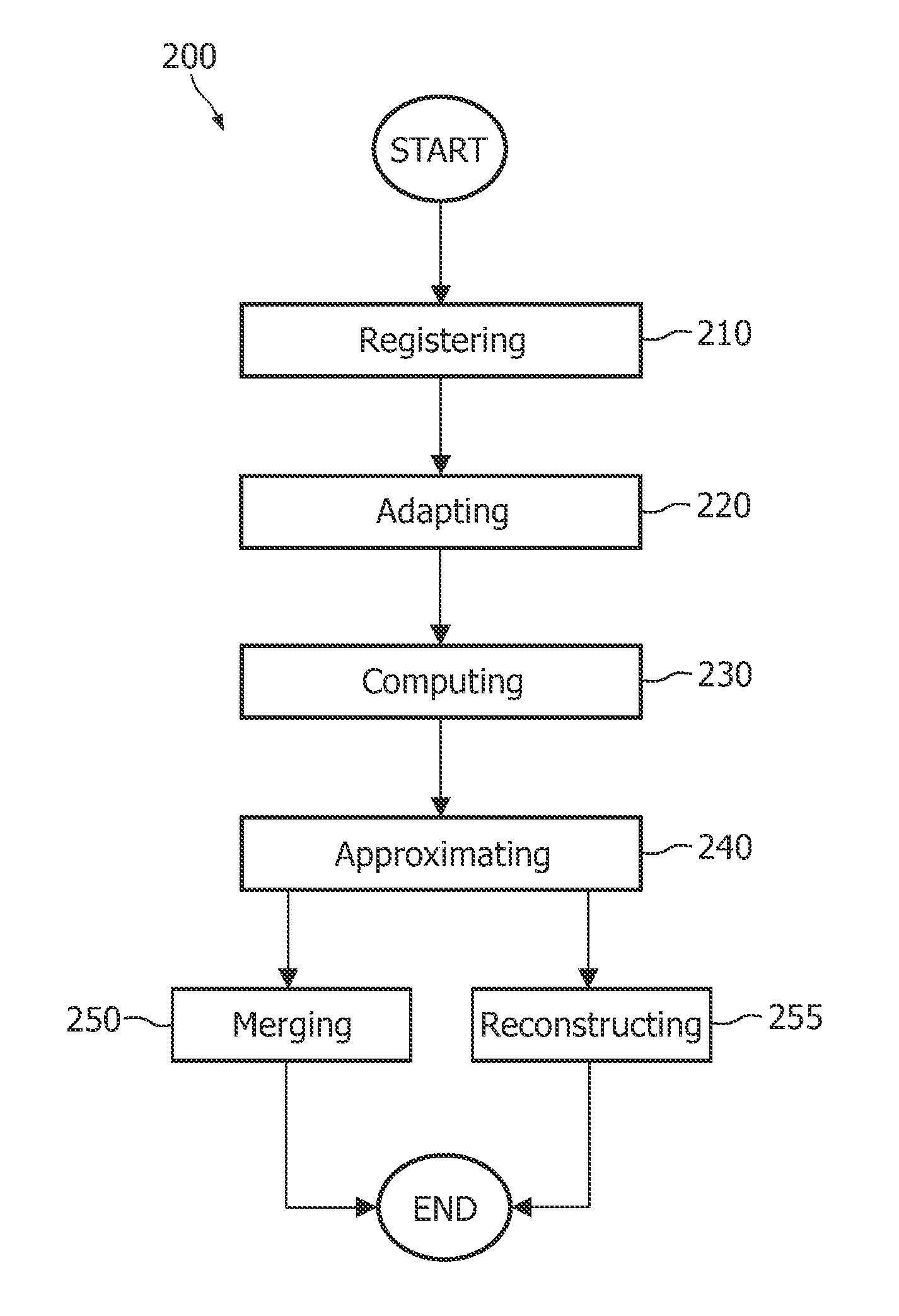
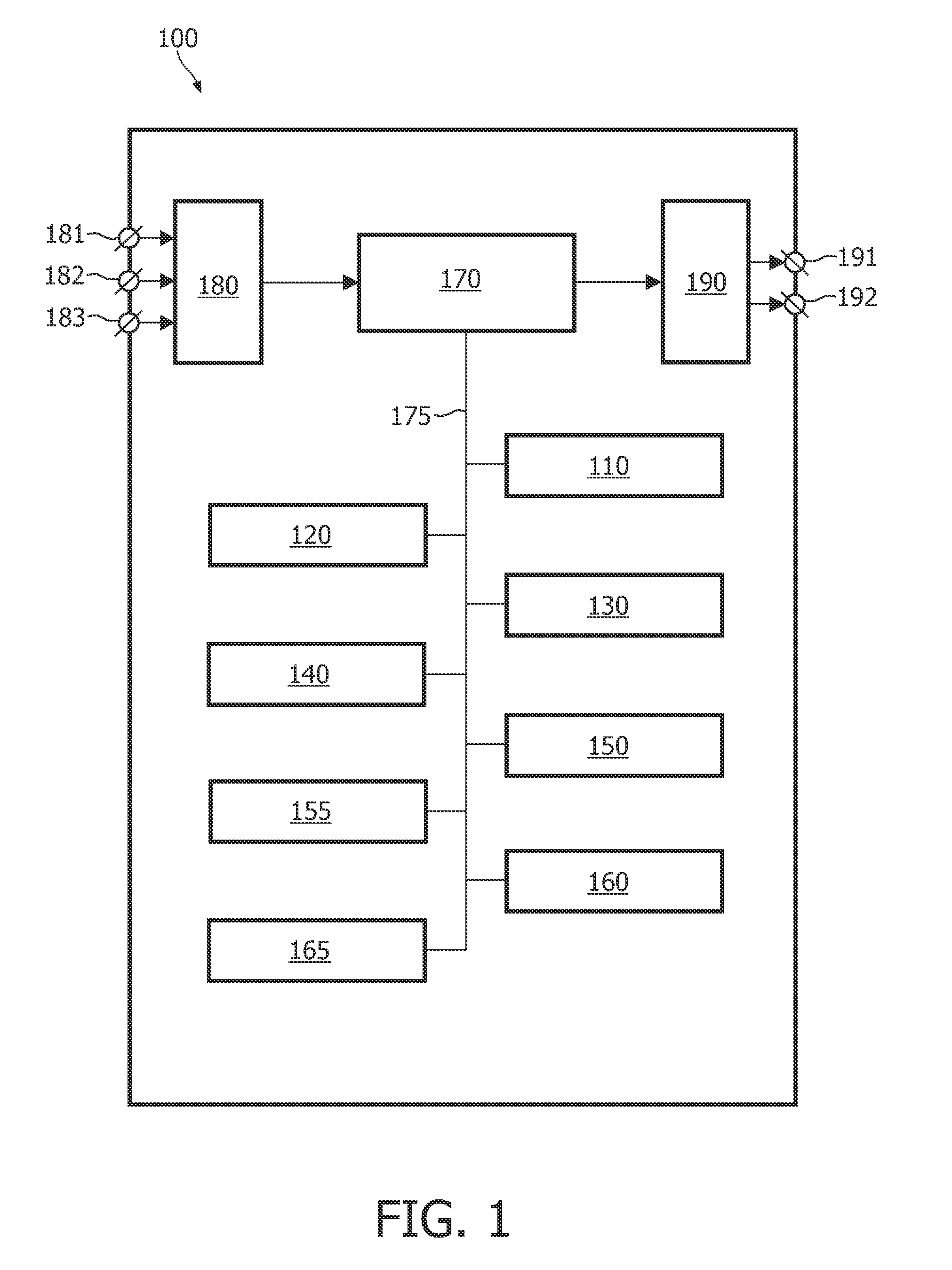
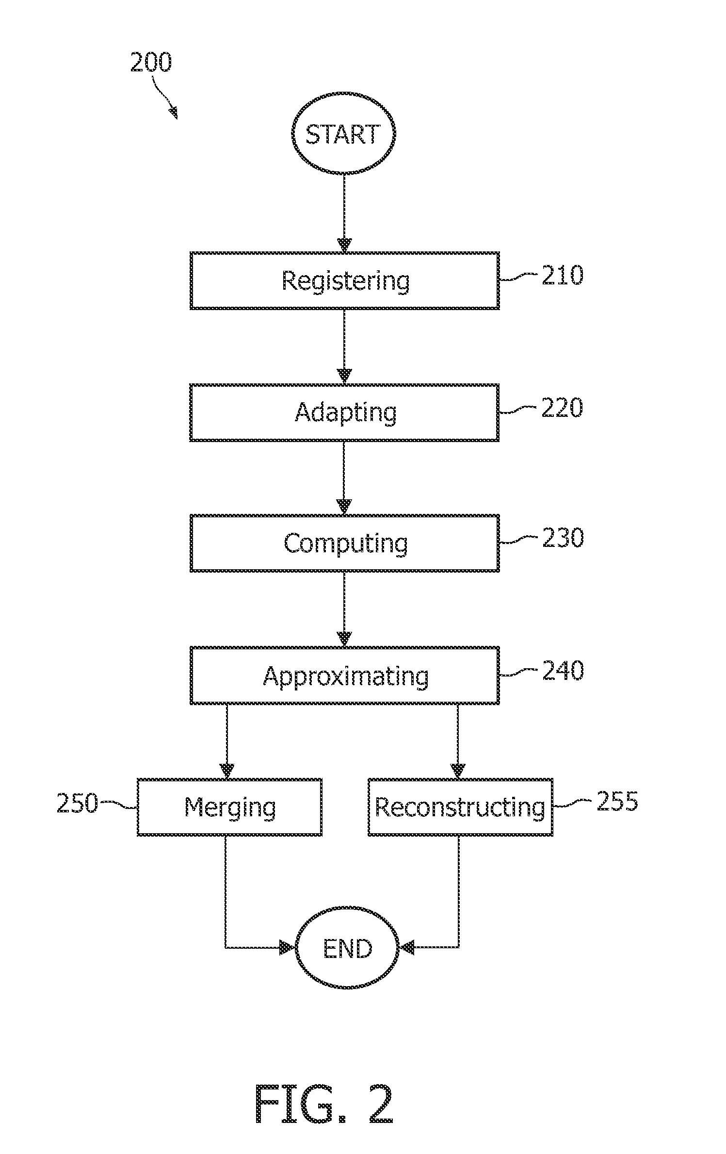
[0039]FIG. 1 is a block diagram of an exemplary embodiment of the system for adapting a first model mesh to first image data and for adapting a second model mesh to second image data, the system comprising:

[0040]a registration unit 110 for registering the first model mesh with the first image data and for registering the second model mesh with the second image data on the basis of a computation of a registration transformation for transforming the first model mesh and for transforming the second model mesh; and

[0041]an adaptation unit 120 for adapting the registered first model mesh to the first image data on the basis of a computation of locations of vertices of the first model mesh and for adapting the registered second model mesh to the second image data on the basis of a computation of locations of vertices of the second model mesh.

[0042]The exemplary embodiment of the system 100 further comprises the following optional units:

[0043]a computation unit 130 for computing a sparse v...


PUM


Abstract

The invention relates to a system for adapting a plurality of model meshes to a plurality of image data. The system has a registration unit for registering the plurality of model meshes with the plurality of image data on the basis of a computation of a registration transformation for transforming the plurality of model meshes, and an adaptation unit for adapting the plurality of registered model meshes to the plurality of image data on the basis of a computation of locations of mesh vertices of the plurality of model meshes. The described system is capable of reducing motion artifacts in tomographic images computed from data acquired at a plurality of different cardiac cycle phases.

Description

FIELD OF THE INVENTION[0001]The invention relates to the field of medical imaging of an anatomical structure and more specifically to the imaging of moving internal tissue such as cardiac tissue.BACKGROUND OF THE INVENTION[0002]Typically thorax image data acquisition occurs in an inhaled or in an exhaled state. The patients hold their breath for the duration of the thorax scan, which prevents breathing motion artifacts, but still the heart is beating. The heart motion results in inconsistencies within the set of projections from which a CT scan is reconstructed. This results in motion artifacts such as tissue dislocation, blurring, and spurious edges. A method of imaging moving tissue is described in US 2005 / 0069081 entitled “Method for Tracking Motion Phase of an Object for Correcting Organ Motion Artifacts in X-Ray CT”. This document describes a method of tracking the motion phase of an object such as a heart. Within the diastole phase of a cardiac cycle there is less motion of th...

Claims


Application Information

Patent Timeline
Patent Type & Authority Patents(United States)
IPC IPC(8): G06K9/00
CPCG06T7/0028G06T7/0089G06T7/2046G06T2200/04G06T2207/10081G06T2207/30048G06T2207/30061G06T2211/412G06T7/33G06T7/149G06T7/251
Inventor BARSCHDORF, HANSVON BERG, JENSKUHN, MICHAEL HARALDLORENZ, CRISTIANBLAFFERT, THOMAS
Owner ELI LILLY & CO
Why Eureka
Try Eureka